October 3, 2024

From the 2024 UPC Illustrated Training Manual, Chapter 8 – INDIRECT WASTES
814.4 Appliance Condensate Drains. Condensate drain lines from individual condensing appliances shall be sized as required by the manufacturer’s instructions. Condensate drain lines serving more than one appliance connecting to a common indirect waste pipe shall have the connections to the indirect waste pipe protected by a sanitary waste valve complying with ASME A112.18.8, condensate trap complying with IAPMO IGC 196, or trap with a trap primer.
Condensing appliances should have means of disposal of the condensation similar to cooling coils. Usually, the manufacturer provides detailed instructions on how to dispose of the condensation, including the minimum size of condensate piping (based on the predicted amounts of condensation).
Since the condensation tends to be corrosive in nature, the installation instructions should be followed closely as to the type of condensate piping material to be used and also what the suitability is of drainage piping material receiving the corrosive discharge.
The primary concern with the connection to indirect waste pipe from multiple condensate drains is the free passage of air between spaces. Without a means of preventing the movement of air in the indirect waste pipe, biohazardous airborne materials can easily migrate between building spaces. Each condensate drain connecting to a common indirect waste pipe must be protected in one of the three ways mentioned, namely with a sanitary waste valve, a condensate trap, or a trap with a trap primer.
These methods would prevent the movement of contaminated air between different spaces in a building. Two devices that would provide the isolation of air movement through an indirect waste pipe are sanitary waste valves and condensate traps and are regulated by ASME A112.18.8 and IAPMO IGC 196 respectively. Both devices will isolate the air movement. To a lesser degree, a water seal trap could provide isolation of air movement. The problem with a trap is that if the trap loses the water seal, the trap provides no protection against air movement. Condensate drains may not operate for months, thus leaving the trap with no source of water for refilling due to evaporation. For that reason, when accepting a water seal trap receiving the discharge from multiple condensate drains, a trap seal primer valve shall also be installed.
From the 2024 UMC Illustrated Training Manual, Chapter 3 – GENERAL REGULATIONS
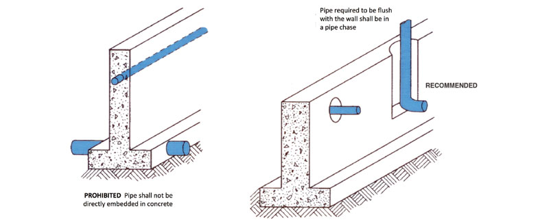
316.2 Installation. Piping or tubing shall be installed so that the piping, tubing, or connections will not be subject to undue strains or stresses, and provisions shall be made for expansion, contraction, and structural settlement. No piping or tubing, unless designed and listed for such use, shall be directly embedded in concrete or masonry. No structural member shall be seriously weakened or impaired by cutting, notching, or otherwise as defined in the building code.
The installation of the mechanical system may require piping through walls and floors, in the ground and under footings, and in many other conditions that could exert pressure or strain on the piping. Care must be taken so that the piping is installed to move freely, preventing structural settlement or expansion and contraction of piping from detrimentally affecting the system. Often, failure of the piping system is caused by the pipe being tightly secured in hangers, straps, or the structure itself. Expansion and contraction of either the pipe or the structure causes the pipe to crack or to slip out of its fittings.
Pipe passing perpendicularly through or parallel within a concrete or masonry wall or floor should always pass through a sleeve or box per Section 316.1. The intent is that piping shall not be located within or pass through concrete walls or slabs where a slight shifting or settlement can result in a major pipe failure. A pipe chase must be provided in the concrete wall when piping is to be recessed. Regardless of the method used to pass pipe through these conditions there must be provisions to allow movement of the pipe. This includes, but is not limited to, slabs, walls or footings. In no case shall the building impose a load on the pipe that could result in breakage or leaks in the piping system. Figure 316.2 shows some recommended and prohibited piping installations.
When pipe passes or is placed within walls, the wall or structure should not be weakened by notching or cutting. The building code has provisions for how much material can be removed from the wall or stud before it is weakened to the point of failure.

PROPER PLACEMENT OF PIPING WITHIN WALLS
(This is not to be considered the official position of IAPMO, nor is it an official interpretation of the Codes.)

IAPMO
IAPMO develops and publishes the Uniform Plumbing Code®,the most widely recognized code of practice used by the plumbing industry worldwide; Uniform Mechanical Code®; Uniform Swimming Pool, Spa and Hot Tub Code®; and Uniform Solar Energy, Hydronics and Geothermal Code™ — the only plumbing, mechanical, solar energy and swimming pool codes designated by ANSI as American National Standards — and the Water Efficiency Standard (WE-Stand)™. IAPMO works with government, contractors, labor force, and manufacturers to produce product standards, technical manuals, personnel certification/educational programs and additional resources in order to meet the ever-evolving demands of the industry in protecting public health and safety.
Last modified: October 10, 2024
