EXAMINING FIRE-RATED ASSEMBLIES, DAMPER SELECTION, AIR CLASSIFICATION, AND SHUTDOWN REQUIREMENTS THAT COMMONLY TRIGGER FIELD CORRECTIONS
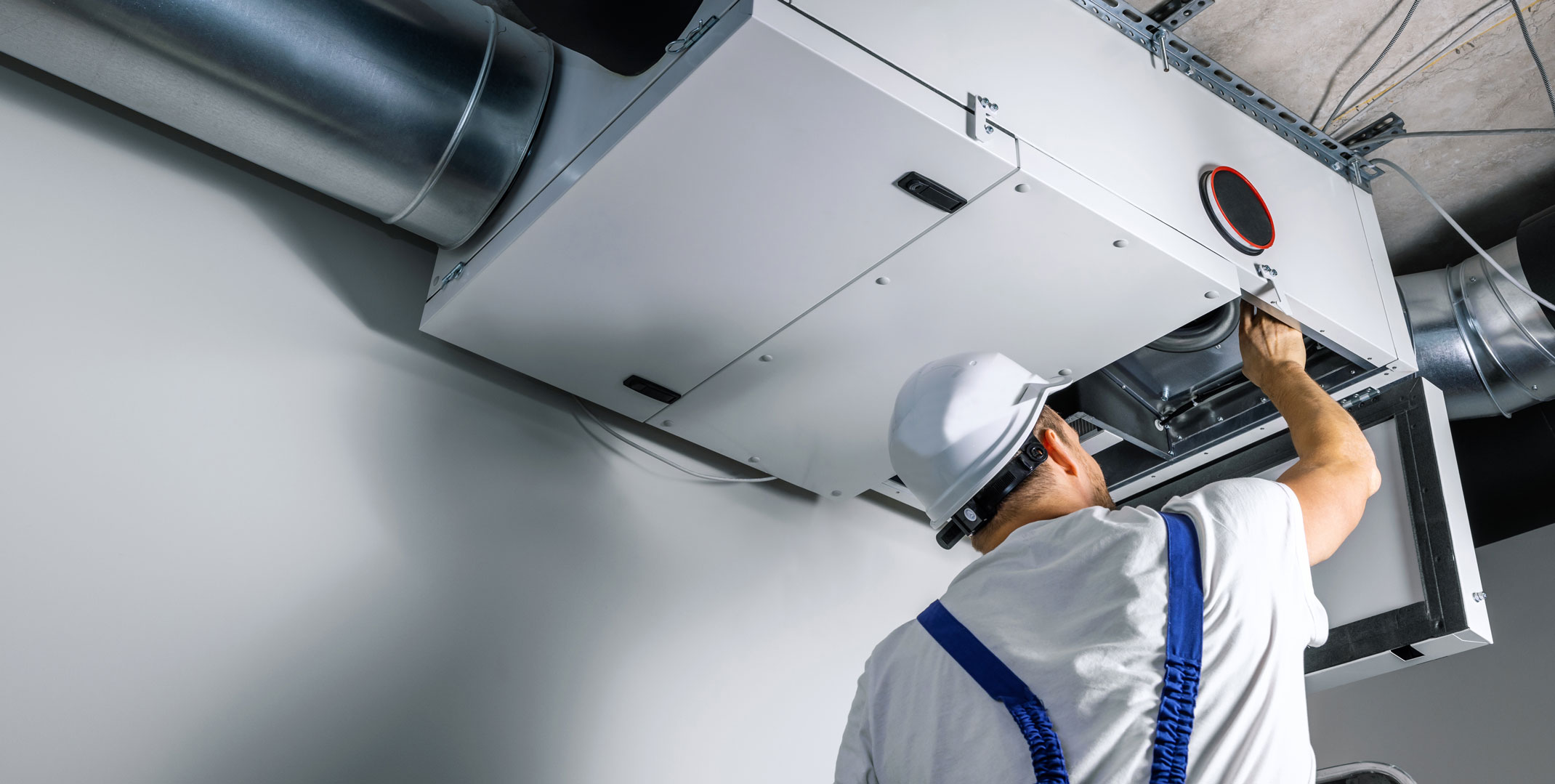
Jesse Kealy and Travis Christensen opened their session at IAPMO’s 2025 Annual Education and Business Conference with a practical goal: to walk inspectors and installers through the mechanical duct and exhaust code requirements they see most often — and the issues that commonly lead to corrections in the field.
Kealy, an HVAC instructor for Plumbers and Pipefitters Apprenticeship Training of Kansas (PPATKS) and now a Mechanical Services project manager for IAPMO, and Christensen, a senior building inspector for Salt Lake City, structured the presentation around real world scenarios drawn from inspections, plan reviews and jobsite experience.
Christensen began by stressing that mechanical systems rarely fall under a single code.
“If you are an HVAC contractor or you are just doing one trade, just try to keep in mind the other codes that may be applicable,” he said. Mechanical installations, he noted, routinely intersect with building, fire, plumbing, electrical and accessibility requirements — and overlooking those intersections can create downstream issues that surface late in a project.
Why Definitions Matter
Before addressing specific systems or components, Christensen emphasized the importance of using precise language — particularly when describing rated assemblies.
“Way too often when I hear that that’s a rated wall, my first question is, ‘Rated toward what?’” he said.
Throughout the session, both presenters returned repeatedly to definitions, explaining that confusion often begins when walls or assemblies are labeled as “rated” without specifying what type of rating applies. Christensen walked through the differences between fire barriers, fire partitions, smoke barriers and smoke partitions, noting that each serves a distinct purpose and carries different requirements.
A fire barrier is a “fire-resistance-rated wall assembly of materials designed to restrict the spread of fire in which continuity is maintained,” Christensen said, explaining that the rating extends from one rated assembly to another. Fire partitions, by contrast, are less restrictive and apply to individual wall sections rather than full assemblies.
“And a big word there is continuity,” he said, “so if you’re thinking about that, you’re going to start at the bottom of the assembly.”
Smoke barriers and smoke partitions serve a different function altogether, focusing on limiting the movement of smoke rather than fire. While the distinctions can appear subtle on paper, Christensen stressed that they directly affect how systems are installed and inspected.
“If you don’t know what wall you’re going through,” he said, “that makes a difference on what we’re going to put through that wall, or if we even can.”
Kealy reinforced the point from an installer’s perspective, cautioning against relying on shorthand descriptions.
“If someone just says it’s a fire-rated wall,” he said, “that tells me absolutely nothing.”
GRAPHICS SOURCED FROM INSTRUCTOR’S ORIGINAL PRESENTATION
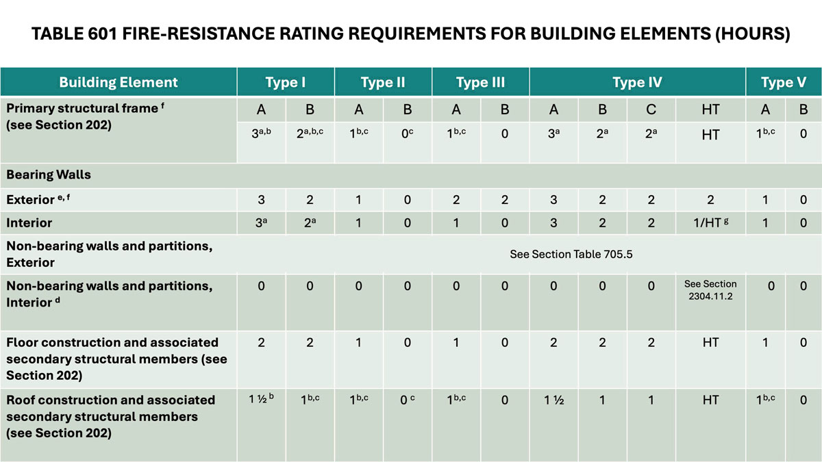
Fire Ratings and Wall Assemblies
UMC DEFINITIONS
- Fire Barrier. A fire-resistance-rated wall or assembly of materials designed to restrict the spread of a fire in which continuity is maintained.
- Fire Partition. An interior wall or partition of a building that separates two areas and serves to restrict the spread of fire but does not qualify as a fire wall.
- Fire Wall. A wall separating buildings or subdividing a building to prevent the spread of the fire and having a fire resistance rating and structural stability. [NFPA 96:3.3.26]
Building on those definitions, the presenters discussed how fire ratings affect mechanical penetrations and damper requirements.
Christensen noted that confusion often arises when walls are labeled generically as “rated” without identifying whether they are fire barriers, partitions or firewalls.
That distinction determines whether ductwork is allowed to pass through an assembly, whether dampers are required, and what type of protection must be provided. Kealy emphasized that installers and inspectors must understand the assembly before selecting materials or methods.
Knowing whether a wall is a barrier, partition or firewall directly affects damper selection, penetration protection and overall code compliance. In practice, those determinations often involve coordination between designers, installers and inspectors — and mistakes can be difficult and expensive to correct once construction is underway.
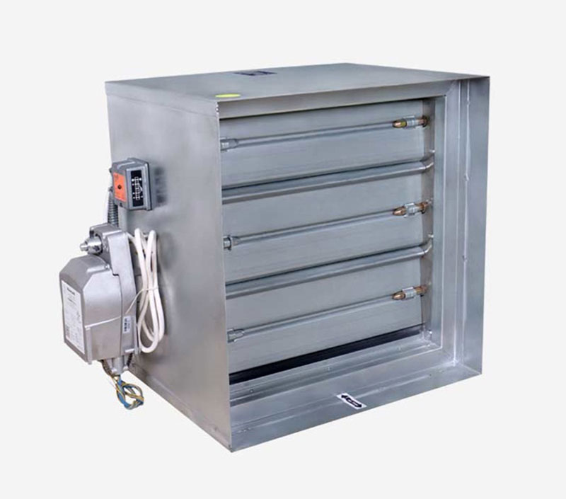
Dampers and System Operation
The session then turned to fire dampers, smoke dampers and combination fire/smoke dampers, with a focus on how they interact with HVAC systems during a fire event. Kealy explained that damper selection must align with how a system is designed to operate.
“The thing we have to remember about a static damper is the system behind it has to shut off if there’s a fire or a smoke event because those dampers are not designed to close under airflow conditions,” he said, “meaning if that blower keeps running, that damper will not close.”
Christensen underscored that shutdown methods matter.
“The code explicitly says cut main power,” he said, describing situations where contractors attempted to rely on thermostat or control power instead.
Dynamic dampers, Kealy explained, are designed to close while air continues to move through the system.
“Dynamic is designed to shut even if the blower is running,” he said.
UMC 606.1, 606.2, 606.3
- Smoke Dampers shall comply with UL 555S, and shall be installed in accordance with the manfacturer’s installation instructions
- Fire Dampers shall comply with UL 555
- Ceiling Radiation Dampers shall comply with UL 555C
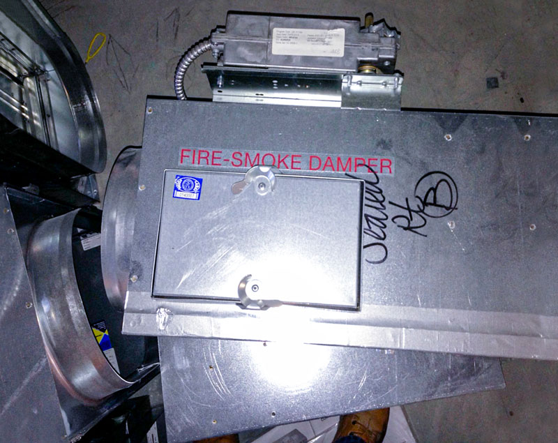
Kealy and Christensen also pointed to UL listings and Uniform Mechanical Code (UMC®) requirements as key verification steps during inspection. Under the UMC, smoke dampers are required to comply with UL 555S, fire dampers with UL 555, and ceiling radiation dampers with UL 555C. Combination fire/smoke dampers must be properly listed and supported by submittal documentation, since labels in the field are often difficult to read after installation.
Access and Coordination Challenges
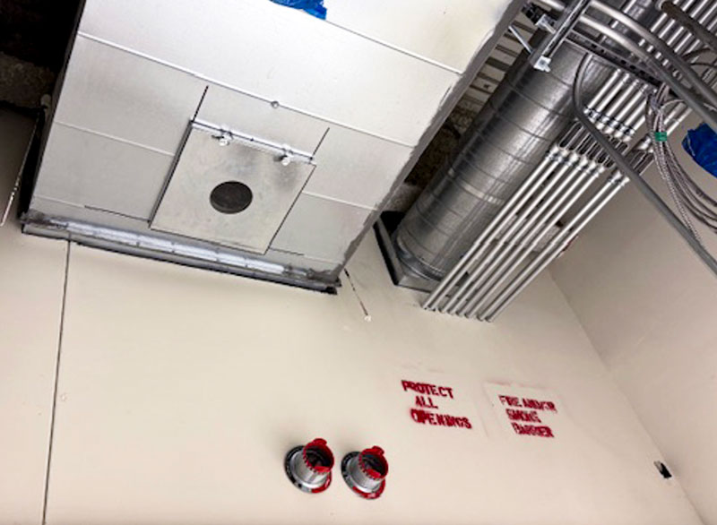
ACCESS UMC 606.8
- Fire and smoke dampers shall be provided with an approved means of access large enough to allow access inspection and maintenance of the damper and its operating parts.
Access to dampers emerged as a recurring issue during the session.
“Access is one of the biggest issues I have. It seems like access is decided in the ninth hour every single time,” Christensen said.
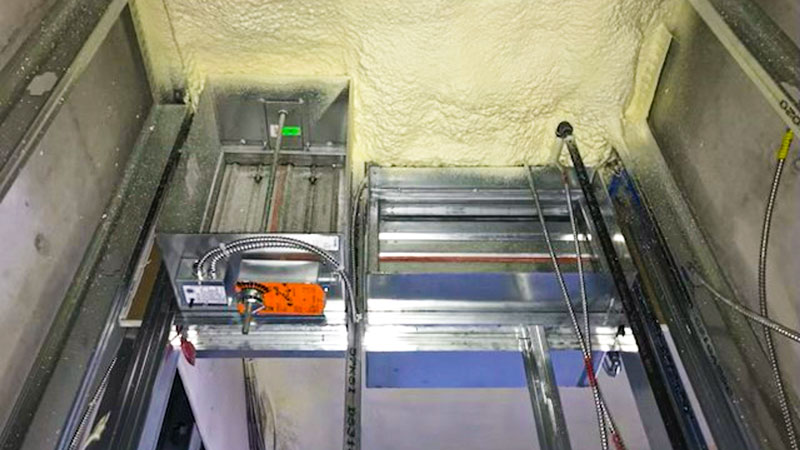
He shared examples where dampers were technically installed but difficult or unsafe to reach, complicating inspection and long-term maintenance. In some cases, access panels were assumed to be adequate until inspectors attempted to locate and verify the dampers in the field.
Christensen also highlighted coordination issues between trades, showing examples where insulation, conduit or wiring interfered with damper operation and inspection.
He acknowledged that while the example he showed probably was going to be a good install, “when a subcontractor wasn’t aware of the requirements, was just going free flow with the foam, it definitely limited the operation on that one.”
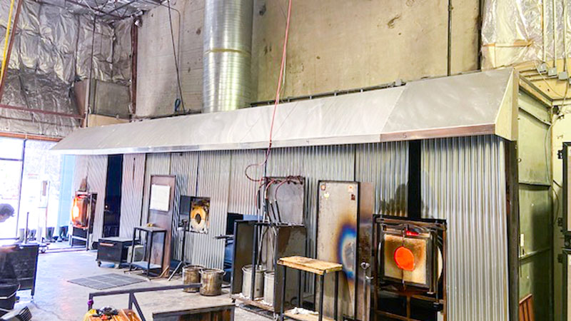
Environmental Air Ducts and Air Class
502.2.1 ENVIRONMENTAL, CLASS 1, AND CLASS 2 AIR DUCTS.
- Environmental, Class 1, and Class 2 air duct exhaust shall terminate not less than 3 feet (914 mm) from a property line, 10 feet (3048 mm) above a public way, 3 feet (914 mm) from openings into the building and the minimum separation distance from ventilation system outdoor air intakes determined in accordance with Section 402.4.1. The discharge of dryer exhaust ducts shall not terminate over a public way or over an area where condensate or vapor could create a nuisance or hazard.
Kealy next reviewed environmental air ducts and changes in the UMC that organize clearance requirements by air class.
“As we go higher in numerical value, the air gets worse and worse and worse,” he said, explaining that Class 1 air is the cleanest and Class 4 the dirtiest.
Those classifications affect termination distances from property lines, building openings and public walkways. Christensen noted that improper classification can result in clearance violations that are difficult to correct after installation.
“We don’t want to shoot a bunch of dirty, nasty air onto a neighbor’s property,” he said.
502.2.2 CLASS 3 AIR DUCTS.
- Class 3 air duct exhaust shall terminate not less than 10 feet (3048 mm) from a property line, 3 feet (914 mm) from exterior walls or roofs that are in the direction of the exhaust discharge, 10 feet (3048 mm) from openings into the building, 10 feet (3048 mm) above adjoining grade, and the minimum separation distance from ventilation system outdoor air intakes determined in accordance with Section 402.4.1.
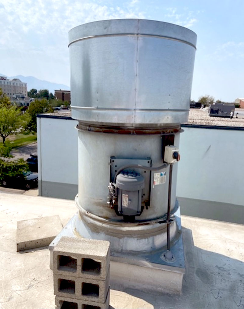
Maintaining proper exhaust fan termination depends on the constituents being exhausted from the system. Technicians need to verify the constituents to lay out proper clearances to property lines, distances from openings into the building, proper distance above grade and proper separation to fresh air intakes.
IMAGE SOURCED FROM INSTRUCTOR’S ORIGINAL PRESENTATION
Kealy noted that Class 3 air represents a middle range within the UMC classifications and may be present in either environmental air ducts or product conveying systems, depending on the type and concentration of contaminants in the duct. As a result, Class 3 air ducts carry greater clearance requirements than cleaner air classifications, particularly at termination points, and must be carefully identified during design and inspection.
502.2.3 PRODUCT CONVEYING, FLAMMABLE, AND CLASS 4 AIR DUCTS
- Ducts conveying Class 4 air or explosive or flammable vapors, fumes, or dusts shall terminate not less than 30 feet (9144 mm) from a property line, 10 feet (3048 mm) from openings into the building, 6 feet (1829 mm) from exterior walls or roofs that are in the direction of the exhaust discharge, 30 feet (9144 mm) from combustible walls or openings into the building that are in the direction of the exhaust discharge, 10 feet (3048 mm) above adjoining grade, and the minimum separation distance from ventilation system outdoor air intakes determined in accordance with Section 402.4.1.
He said Class 4 air represents the highest level of concern under the UMC, typically involving air that contains flammable vapors or highly contaminated exhaust. Because of that risk, Class 4 air ducts are subject to the most restrictive termination and clearance requirements, including increased separation distances from property lines and building openings. Proper classification at the design stage is especially important, he noted, since correcting a Class 4 termination after installation can be difficult and costly.
“This is the dirtiest air that we can define in the UMC,” Kealy said. “So now we’re jumping, if it’s a flammable vapor constituent, we jump to 30 feet from a property line.”
Dryer exhausts, locker rooms, shower rooms and janitor closets were discussed as systems that fall under environmental air duct provisions. Kealy noted that misunderstanding those classifications often leads to improper terminations.
“If you don’t know what that is,” he said, “you’re going to have some struggles.”
Product Conveying Systems
The presenters also addressed product conveying systems — ducts used to transport particulates, flammable vapors or corrosive materials.
“If it’s toxic, flammable or particulate material, it’s going to be a product conveying system,” Kealy said.
He noted that product conveying systems are defined by what they carry, not just operating temperature. While ducts operating above 250 F are classified as product conveying systems, many systems qualify based on the materials conveyed even at lower temperatures.
Christensen shared examples from manufacturing and agricultural facilities, emphasizing the importance of design documentation and, in some cases, third party evaluation to determine hazards.
“A lot of products you wouldn’t expect to be flammable would surprise you,” he said. The discussion highlighted how assumptions about materials — particularly dusts and byproducts — can lead to misclassification and safety risks if not properly evaluated.
Plenums and Flame Spread
PLENUM
- 602.2 Combustibles Within Ducts or Plenums. Materials exposed within ducts or plenums shall be noncombustible or shall have a flame spread index not to exceed 25 and a smoke-developed index not to exceed 50, where tested as a composite product in accordance with ASTM E84 or UL 723. Plastic piping installed in plenums shall be tested in accordance with all requirements of ASTM E84 or UL 723. Mounting methods, supports and sample sizes of materials for testing that are not specified in ASTM E84 or UL 723 shall be prohibited.
Plenum spaces and flame spread index requirements were also reviewed, with an emphasis on material selection.
“Flame spread index is a range,” Kealy said. “When we say it can’t exceed 25, that doesn’t mean it has no flammability — just limited flammability.”
Christensen emphasized that materials installed in plenums must be listed and labeled for that use to limit the spread of smoke and fire.
“We’re trying to prevent toxic smoke from being spread throughout the space,” he said.
Automatic Shutdown Requirements
AUTOMATIC SHUTOFF
- 609.1 Air-Moving Systems and Smoke Detectors. Air-moving systems supplying air in excess of 2000 cubic feet per minute (ft3/min) (0.9439 m3/s) to enclosed spaces within buildings shall be equipped with an automatic shutoff. Automatic shutoff shall be accomplished by interrupting the power source of the air-moving equipment upon detection of smoke in the main supply-air duct served by such equipment.
Automatic shutdown thresholds for air moving systems were another focal point.
“Anything above 2,000 CFM needs automatic shutoff,” Kealy said, translating that requirement into tonnage equivalents familiar to contractors.
Christensen stressed that automatic shutdown is not just a mechanical consideration, but one that often requires coordination with electrical systems. He noted that the UMC specifies shutdown at the main power source rather than through control wiring alone, and that confusion over this distinction frequently leads to corrections during inspection.
Christensen noted that exceptions exist but must be clearly supported by code language and manufacturer instructions.
“We’ve got to read the whole code,” Kealy said. “You can’t stop at one section.”
Practical Takeaways
Throughout the session, Kealy and Christensen repeatedly returned to the importance of definitions, access and coordination across trades. Their examples illustrated how code requirements that appear straightforward on paper can become complicated once systems intersect with walls, ceilings and other building elements.
Kealy encouraged attendees to slow down and verify requirements when questions arise.
“If you don’t know what you’re looking at,” he said, “go back to the code.”

Mike Flenniken
Mike Flenniken is a staff writer, Marketing and Communications, for IAPMO. Prior to joining IAPMO in 2010, Flenniken worked in public relations for a group of Southern California hospitals and as a journalist in writing and editing capacities for various Southern California daily newspapers.
Last modified: April 14, 2026