An unwanted or undesirable reversal of flow in a piping system is simply known as backflow. Because fluids generally flow from high pressure to low pressure, the hydraulics of backflow can occur as either:
- Elevated plumbing or system pressure known as backpressure, or
- A pressure below 0 psig creating a siphon or backsiphonage in the piping system
A piping system such as potable water will experience fluids moving back and forth for a number of reasons. This movement may result from hydraulic shock (water hammer) or simply maintaining or balancing the pressure. Backflow does not necessarily mean the plumbing system will be contaminated or polluted. A risk of contamination or pollution occurs when a physical link is established between the source and another type of fluid. This is known as a cross-connection. The combination of backflow and the cross-connection are necessary for a water system to become non-potable.
The best way to prevent backflow is to maintain a physical separation between the piping systems. However, with modern fixture and appliance technology, a separation like an air gap is not always an option. In that case, the cross-connection must be controlled with a device or an assembly.
A mechanical cross-connection control measure will provide protection from backsiphonage or either backpressure or backsiphonage. Those that prevent a siphon in the piping system are known as vacuum breakers.
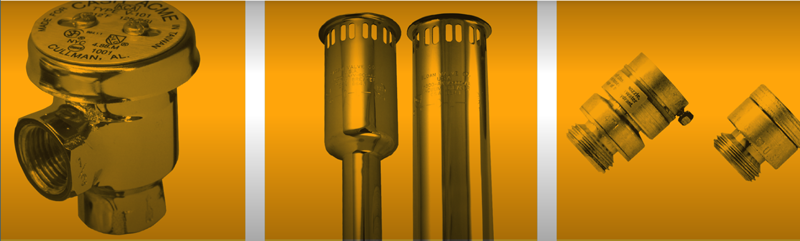
Vacuum Breakers

A vacuum breaker may be a device, such as an atmospheric vacuum breaker (AVB), without shut-off valves or test cocks. These devices will typically be installed at hose bibbs, flushometers, and utility sinks, as examples. An AVB has a number of operational limitations that must be followed for it to function correctly. These limitations include: 1) The device must be installed a minimum of six inches above the highest outlet (deck-mounted devices may be one inch); 2) There can be no valves from the outlet of the AVB; 3) Water pressure cannot be applied for more than 12 hours in a 24-hour period; and 4) There can be no elevated pressure at the outlet.
The more robust vacuum breakers are the assemblies. The pressure type and spill-resistant assemblies have mechanically loaded check valves and air-inlet valves. These assemblies include test cocks and isolation valves for field testing and maintenance. Like the devices, the assemblies also have some operational limitations. These include: 1) The assemblies must be installed 12 inches above the ground and above the outlet use; and 2) There can be no elevated pressure at the outlet. Installation advantages include outlet shut-off or control valves are allowed, and the assembly can be used with continuous pressure.
Whether the vacuum breaker is a device or an assembly, they are considered appropriate protection for both health (high) hazard and non-health (low) hazard applications.
 Double Check Valve Assembly
 Reduced Pressure Principle Assembly
 Dual Check Valve with Intermediate Vent
 Dual Check Valve
DCVs and RPs
As the name double check valve assembly (DCVA) suggests, it consists of two check valves in series and an isolation valve at the inlet and outlet. The units also contain four properly located test cocks for field tests on installation and at least annually thereafter. This assembly is used for non-health (low) hazard applications. The primary reason is that the unit has no external indication of an internal failure, such as a vent discharge.
The DCVA must be installed a minimum of 12 inches above the surrounding ground or floor, and proper side clearances must be allowed for testing and maintenance. Generally, DCVAs are installed horizontally. If a vertical flow up or down orientation is required, the assembly must be laboratory tested and approved for the orientation.
A DCVA may be installed on the service line to the building as water utility (containment) protection. Be mindful that backflow preventers installed in series will have a cumulative pressure loss for the system. For example, if the maximum allowable loss from a DC on a domestic system is 10psi, another DCVA elsewhere in the building will add another 10psi to the total loss. What will the residual pressure be at the outlet of the second DCVA given a 20psi reduction from the supply pressure?
Some model codes require that a permanent platform be installed to access the backflow preventer if it is installed more than five feet above the floor. Any installation in a pit or vault should be avoided if the vault is subject to flooding. Remember that test cocks are water outlets, and when submerged are technically a cross-connection.
A reduced pressure principle assembly (RP) is the second backflow preventer that provides protection from backpressure and backsiphonage. At first glance, it is similar in appearance to a DCVA with the exception of a hydraulically independent relief valve. The valve will vent fluid between the two checks to the atmosphere when an internal failure occurs. Because of this feature, an RP is considered adequate protection for both health (high) and non-health (low) hazard applications.
Whether the RP is installed as a service connection (containment) backflow preventer or a point-of-use (isolation) assembly, several issues must be taken into consideration. As mentioned above, the assembly will discharge a significant volume of water/fluid. For example, a four-inch (NPS) assembly installed at a location with 75psi line pressure may discharge 500 gpm given a catastrophic failure. Most small buildings are not provided an 8-inch drain to accommodate that flow. Further, what fluid is being discharged? Can it flow to the sanitary sewer or must it be captured and treated prior to its release?
Because of the potential relief valve discharge, RPs will not be located in pits or vaults. When the relief valve is submerged, a cross-connection exists where fluid may aspirate into the piping system.
An RP will almost always be installed horizontally. Like the DC, if it is installed in a vertical orientation, it must be tested and approved for that design. The product performance standard contains a requirement that the relief valve outlet must be lower than the lowest point of the inlet check to provide drainage and no ponding at the check valve outlet.
Double check detector assemblies (DCDA) and reduced pressure detector assemblies (RPDA) are a special type of backflow preventer built primarily for the fire-sprinkler market. These units are two DCVAs or RPs constructed in parallel with the bypass containing a flow meter that will register flows up to 2 gpm. The purpose of the meter is to detect small leaks in the system or possible usage by the owner.
Recently, the industry developed a Type II detector assembly. The bypass on the unit contains a check, control valve, and water meter. This bypass is piped from the inlet to the outlet of the mainline second check valve.
ASSE International maintains product performance standards for several backflow prevention devices. These include (but are not limited to):
- Water supply fed trap primers
- Flushometer vacuum breakers
- Dual check valves (typically found on residential service connections)
- Dual check valves with an intermediate vent (low-pressure residential boilers)
- Carbonated and other beverage dispensers
- Hose bibb and hydrant vacuum breakers
- Chemical dispensers for cleaning stations
Please remember that these products have been developed for specific uses. It is important to understand how and why they work. A low-pressure residential boiler device is not an RP simply because it has two check valves and a vent. Indeed, this device is considered non-health (low) hazard protection.
If you have any questions regarding the use or application of any backflow preventer, consult with your local Authority Having Jurisdiction or contact ASSE International. Remember that these products protect the health and safety of building occupants and users of the public’s water system.
Article by Dr. Stu Asay, PE first appeared in Working Pressure magazine
Last modified: December 19, 2023