February 6, 2025

From the 2024 UPC Illustrated Training Manual, Chapter 7 – SANITARY DRAINAGE
710.5 Size of Building Drains and Sewers. Building drains or building sewers receiving a discharge from a pump or ejector shall be adequately sized to prevent overloading. Two fixture units shall be allowed for each gallon per minute (L/s) of flow.
Discharges from a sewage pump system will eventually connect to the building’s gravity drainage system. In order to prevent this high-volume, high-velocity discharge from overloading the gravity drain lines, it is necessary for a fixture unit rating to be established that provides for this “continuous flow” (see commentary in Section 702.3 for more discussion on continuous flow). Both this section and 702.3 stipulate that all pump discharges shall be assigned two fixture units for each gallon per minute of discharge. Therefore, a pump that is designed to have a 20 gpm discharge rate would impose a 40-fixture unit load on the gravity drain line at the point where the pump discharge piping is connected to the gravity system.
Where more than one pump is installed (as required in public-use buildings according to Section 710.9) the fixture unit loading is based upon the discharge from one pump rather than both due to redundancy. Section 710.9 requires an arrangement of alternate function between the two pumps and simultaneity will only occur in an overload condition where an alarm will sound. Hence, a properly designed system will seldom, if ever, have both pumps discharging.
In the event of an emergency condition that requires both pumps to operate simultaneously, the resulting combined discharge will normally be short-lived. The increased loading, resulting from the combined output of both pumps, will represent only a proportion of the combined discharge flow rates. The combined discharge will not represent an amount that is twice their separate capacity. This is because friction pressure loss is proportional to the square of the flow rate (F=KV2). With two pumps operating in parallel, the flow rate doubles, whereas the friction pressure loss is exponential. Therefore, the output discharge is a proportion of the combined flow rates. A system curve shows the relationship between flow rate and pressure loss and determines the flow rate when two pumps operate in parallel. Figure 710.5 shows a system curve intersecting a single operating pump at 320 gpm and two pumps in parallel at 400 gpm.
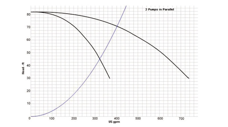
SYSTEM CURVE FOR PARALLEL PUMPS
In all cases, the load imposed at the point of pump discharge connection to the gravity system will be added to the existing gravity fixture unit load created by fixtures installed upstream from the point of connection.
The aggregate total will seldom represent the maximum fixture unit capacity of the pipe to which the pump system is being connected. Sizing tables that illustrate maximum capacity (fixture unit loading) for various pipe sizes reflect enormous incremental changes with each increase in pipe size. There would nearly always be surplus capacity to take up the excess load when both pumps go into action during an emergency condition. However, designers should increase the gravity pipe size if the drainage system loading appears to be near its capacity and when there is concern that activation of both pumps might pressurize the gravity system.
From the 2024 UMC Illustrated Training Manual, Chapter 5 – EXHAUST SYSTEMS
508.4 Supports. Hoods shall be secured in place to resist lateral loads by noncombustible supports. The supports shall be capable of supporting the expected weight of the hood plus 800 pounds (362.9 kg).
Lateral loads are live loads that are applied parallel to the ground; that is, they are horizontal forces acting on a structure and equipment. They are different to gravity loads, for example, which are vertical, downward forces. Significant lateral loads can be imposed on a structure during earth pressure, such as settlement, wind loads, water pressure, and earthquakes. Buildings, especially in areas of seismic activity, need to be carefully designed to ensure they do not fail if lateral loads should occur. Bracing can be used to resist lateral loads. The beams and columns of a braced frame structure carry vertical loads, while the bracing carries the lateral loads.
(This is not to be considered the official position of IAPMO, nor is it an official interpretation of the Codes.)

IAPMO
IAPMO develops and publishes the Uniform Plumbing Code®,the most widely recognized code of practice used by the plumbing industry worldwide; Uniform Mechanical Code®; Uniform Swimming Pool, Spa and Hot Tub Code®; and Uniform Solar Energy, Hydronics and Geothermal Code™ — the only plumbing, mechanical, solar energy and swimming pool codes designated by ANSI as American National Standards — and the Water Efficiency Standard (WE-Stand)™. IAPMO works with government, contractors, labor force, and manufacturers to produce product standards, technical manuals, personnel certification/educational programs and additional resources in order to meet the ever-evolving demands of the industry in protecting public health and safety.
Last modified: February 6, 2025