April 18, 2024

From the 2024 UPC Illustrated Training Manual, Chapter 10 – TRAPS AND INTERCEPTORS
1002.1 Vent Pipes. Each plumbing fixture trap, except as otherwise provided in this code, shall be protected against siphonage, backpressure, and air circulation shall be assured throughout the drainage system using a vent pipe installed in accordance with the requirements of this code.
This section (see also Section 901.2) requires the trap to be protected from siphonage and backpressure by a vent (see Figure 1002.1), and that air circulation is assured throughout the system. Most of the measures to accomplish this are discussed in Chapter 9 and should be reviewed along with this chapter.
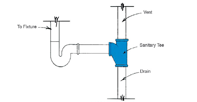
TRAP PROTECTED BY VENT
The protection of the waterseal trap is assured upon a simple pneumatic principle, namely, equal atmospheric pressure must be maintained on both sides of the trap. When a trap is filled, the atmospheric pressure on the fixture side of the trap water seal is equal to the atmospheric pressure on the outlet side of the trap water seal. The vent connection to the trap arm maintains that equal pressure on the outlet side of the trap. As is discussed in Chapter 9, the vent system is designed to maintain pressure variation within the system of plus or minus one-inch water column (0.25 kPa). Pressures above or below that design pressure will cause a trap to lose its water seal. A positive pressure on the downstream side of the trap will cause air to blow through the trap seal, pushing its contents into the fixture. A negative pressure will siphon the trap seal into the trap arm and the drain.
This allowable pressure variation of ± one-inch water column is a considerable factor of safety for a trap seal of 2 inches or greater. For example, if a trap seal has a depth of 2 inches (see Figure 1005.1) and is subjected to a negative pressure of one-inch water column, then the remaining trap seal depth would be 1½ inches. If the trap seal is 4 inches, then the remaining seal depth would be 3½ inches. Hence, it would take a negative pressure of a four-inch water column to siphon the water from a trap with a 2-inch seal below the dip of the trap, and eight-inches of water column to siphon a 4-inch seal below the dip of the trap. Designing a venting system according to Chapter 9 ensures considerable safety margins by maintaining the pressure variations within ± one-inch water column.
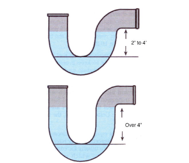
STANDARD TRAP SEAL AND DEEP SEAL TRAP
From the 2024 UMC Illustrated Training Manual, Chapter 8 – CHIMNEYS AND VENTS
803.1.7 Connection to Chimney Liners. Connections between chimney liners and listed double-wall connectors shall be made with listed adapters designed for such purpose. [NFPA 54:13.1.8]
Guidance is provided for using exterior chimneys (see Figure 803.1.7) for heating appliances. These restrictions are needed because of the high heat loss in chimneys exposed to the outdoors below the roofline in cold climates. These restrictions do not apply to chimneys and vents not exposed to the outdoors below the roofline because these chimneys and vents are considered to be interior chimneys.
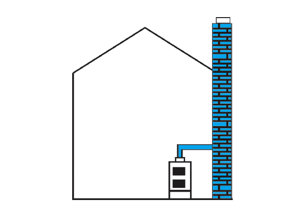
EXTERIOR CHIMNEYS
The following items are required when sizing exterior masonry chimneys:
To size chimneys and vents serving only water heaters, the outdoor design temperature must be greater than 5°F (15°C). In colder climates, either the chimney must be lined with a metallic liner or another vent must be used.
To size chimneys and vents serving space heating appliances, use Table 803.2(7) for the minimum capacity and use Table 803.2(8) for the combined vent capacity of all appliances providing heat to a building.
Note that only B-vent connectors are allowed to minimize heat loss through vent connectors.
Water heaters are treated differently from heating appliances because their total operating hours are not sufficient to keep a chimney warm in cold periods, resulting in condensation of water in the chimney vent.
(This is not to be considered the official position of IAPMO, nor is it an official interpretation of the Codes.)

IAPMO
IAPMO develops and publishes the Uniform Plumbing Code®,the most widely recognized code of practice used by the plumbing industry worldwide; Uniform Mechanical Code®; Uniform Swimming Pool, Spa and Hot Tub Code®; and Uniform Solar Energy, Hydronics and Geothermal Code™ — the only plumbing, mechanical, solar energy and swimming pool codes designated by ANSI as American National Standards — and the Water Efficiency Standard (WE-Stand)™. IAPMO works with government, contractors, labor force, and manufacturers to produce product standards, technical manuals, personnel certification/educational programs and additional resources in order to meet the ever-evolving demands of the industry in protecting public health and safety.
Last modified: April 10, 2024
