
CHANGES FROM THE 2021 UPC TO THE 2024 UPC
Story be Geoff Bilau
CONTENT DISCLAIMER: The information herein is provided for educational purposes only and shall not be treated as an official interpretation of the referenced codes or standards. Always refer to the complete code or standard when installing, replacing, or repairing any plumbing or mechanical system.
Presented by Des Moines, Iowa, chief plumbing inspector and IAPMO Board of Directors member Brian Hamner, the Uniform Plumbing Code® (UPC®) seminar at IAPMO’s 93rd annual Education and Business Conference discussed provisions of the UPC that are different from 2021 to 2024.
An Iowa native, Hammer has 26 years of experience in the plumbing trade. He began his career as a sprinkler fitter with a small company for several years before switching to plumbing. Following stints with Cook Plumbing Corp. and Golden Rule Plumbing and Heating, he began working for Des Moines in 2007 and was promoted to chief plumbing inspector in 2023.
This article will provide a brief recap of his seminar.
202.0 Definition of Terms.
202.1 General. The definitions of terms are arranged alphabetically according to the first word of the term.
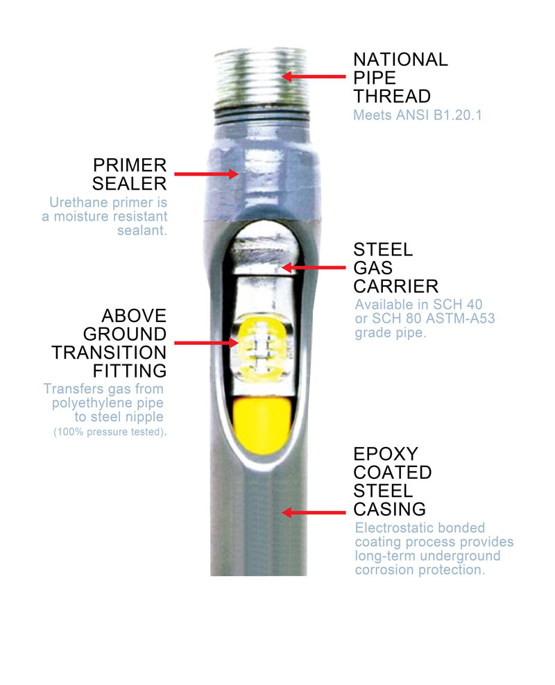
Anodeless Riser. An assembly of steel‐cased plastic pipe used to make the transition between plastic piping installed underground and metallic piping installed aboveground. [NFPA 54:3.3.3]
“In the mechanical code, we had a definition, right?” Hamner said. “But in the plumbing code we didn’t. So, we’ve correlated the two codes.”
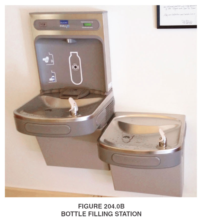
Water Station. A designated location intended to provide access to drinking water through a device or appliance.
“This is a good one because I know a member of my plan review staff asked ‘What’s a water station?” because we didn’t have a definition before even though we had the provisions to allow for water stations,” Hamner said.
301.6 Tall Wood (Mass Timber) Buildings. Plumbing systems installed in tall wood (mass timber) buildings, shall comply with the following:
(1) Be designed by a licensed plumbing contractor or a registered design professional in accordance with this code and the building code.
(2) Be designed to accommodate expansion, contraction, and differential movement between parts of a tall wood (mass timber) building in accordance with Section 312.2.
“The building codes have provisions for these mass timber buildings and we needed to have something in the plumbing code to provide for designing these buildings because when you’re putting them together what’s wood going to do? It’s going to expand and contract, right?” Hamner asked. “So, we need to design these plumbing systems to anticipate the expansion and contractions over time.”
310.9 Female Plastic Connections. Female plastic tapered (NPT) threaded connections shall not be allowed to be used when threaded onto a male metallic connection.
Exception: Female plastic parallel (straight) threaded connections shall be permitted.
“Everybody knows when you take a female connection and you thread in metallic pipe expansion happens,” Hamner said. “So, now we have a provision that does not allow you to use a female plastic connector and screw in a metallic MIP; except female plastic parallel threaded connections,” he said.
310.10 ABS and PVC Transition Joints. Except as provided in Section 705.9.4, PVC and ABS pipe and fittings shall not be solvent welded to dissimilar material.
“This means basically the only place we can have an ABS and PVC solvent weld transition would be outside the building, between the building drain and the building sewer,” Hamner said.
404.2 Overflows. Where a fixture is provided with an overflow, the overflow shall comply with Section 404.2.1 or Section 404.2.2.
404.2.1 Sinks, Lavatories, and Bathtubs. The waste shall be so arranged that the standing water in the fixture shall not rise in the overflow where the stopper is closed or remain in the overflow where the fixture is empty. The overflow pipe from a fixture shall be connected to the house or inlet side of the fixture trap.
404.2.2 Water Closets and Urinals. Overflows on flush tanks shall be permitted to discharge into the water closets or urinals served by them.
“This got changed around over various cycles of code changes,” Hamner said. “There was some disagreement about the differences between an overflow fixture like a sink versus a water closet or urinal. So, now here we go, we’ve got two new sections.”
408.4.3 Temperature‐Actuated, Flow‐ Reduction Devices for Individual Fixture Fittings. Temperature‐actuated, flow‐reduction devices, where installed for individual fixture fittings, shall comply with ASSE 1062. Such devices shall not be used alone as a substitute for the balanced pressure, thermostatic or combination shower valves requirements or as a substitute for bathtub or whirlpool tub water temperature‐limiting valves requirements.
“This was put in the 2021 code as an option,” Hamner said. “The bad thing was if you read the standard for these they are not to be used as a lone single devide, you have to use it in conjunction with all these other devices that will do the tempering downstream first.”
408.8.5 Tests for Shower Receptors. Shower receptors shall be tested for watertightness by filling with water to a depth of not less than 2 inches (51 mm) for not less than 15 minutes. Where no threshold is present, a 2 inch (51 mm) barrier shall be temporarily constructed for testing. The test plug shall be so placed that both upper and under sides of the subpan shall be subjected to the test at the point where it is clamped to the drain.
“We’ve got a lot of people putting in these great big bathrooms where the bathroom is all a shower,” he said. “So, you can sit on the toilet and take a shower at the same time or brush your teeth at the same time. The code asks for a shower pan test and we go, ‘Well, what do we do?’ Normally on a regular shower we have a two-inch threshold, right?”
411.3 Water Closet Seats. Water closet seats shall be properly sized for the water closet bowl type, and shall be of smooth, non‐ absorbent material. Seats, for public use, shall be of the elongated type and either of the open front type or have an automatic seat cover dispenser. Water closet seats shall be provided with or without covers. Plastic seats shall comply with IAPMO/ANSI Z124.5.
“What did we just go through? A pandemic, right?” Hamner said. “And what did we learn about how it spread, one of the ways it spread? Through the air, vapor plume. So, now you can have a toilet seat with a lid on it. People were confused whether you could or couldn’t. Now we just have to train people when you’re done using the bathroom to put the lid down before you flush the toilet.”
417.7 Head Shampoo Sink Faucets. Head shampoo sink faucets shall be supplied with hot water that is limited to not more than 120°F (49°C). Each faucet shall have integral check valves to prevent crossover flow between the hot and cold water supply connections. The means for regulating the maximum temperature shall be in accordance with one of the following:
(1) A limiting device conforming to ASSE 1070/ASME A112.1070/CSA B125.70.
(2) A water heater conforming to ASSE 1084.
(3) A temperature‐actuated, flow‐reduction device conforming to ASSE 1062.
“We actually had this amended in our State of Iowa Plumbing Code for many years,” Hamner said. “So, IAPMO caught up with Iowa.”
417.8 Footbaths and Pedicure Baths. The water supplied to specialty plumbing fixtures, such as pedicure chairs having an integral foot bathtub and footbaths, shall be limited to not more than 120ºF (49ºC) by a water‐ temperature limiting device that conforms to ASSE 1070/ASME A112.1070/CSA B125.70 or by a water heater complying with ASSE 1084.
“So, same thing there, we’re protecting our feet from getting scalded,” he said.
422.1.1 Fixture Calculations. The minimum number of fixtures shall be calculated at 50 percent male and 50 percent female based on the total occupant load. Where information submitted indicates a difference in the distribution of the sexes such information shall be used to determine the number of fixtures for each sex. Once the occupancy load and occupancy are determined, Table 422.1 shall be applied to determine the minimum number of plumbing fixtures required. Where applying the fixture ratios in Table 422.1 results in fractional numbers, such numbers shall be rounded to the next whole number. For multiple occupancies, fractional numbers shall be first summed and then rounded to the next whole number. For toilet facilities designed for use by all genders, the minimum number of fixtures shall be the aggregate calculated at 50 percent female and 50 percent male in accordance with Table 422.1. Where all‐gender fixtures are provided in addition to separate men’s and women’s facilities, those fixtures shall be included in determining the number of fixtures provided in an occupancy.
“So, if we have an area over here that we want to do all gender, and we want separate men’s and women’s restrooms over there, we can take those numbers from the all gender and the separate men’s and women’s restrooms for the full occupancy,” Hamner said.
507.5 Drainage Pan. Where a water heater is located in an attic, in or on an attic ceiling assembly, floor‐ceiling assembly, floor‐subfloor assembly or where damage results from a leaking water heater, a watertight pan of corrosion‐resistant materials shall be installed beneath the water heater in accordance with the following:
(1) The drainage pan shall be provided with not less than 3⁄4 of an inch (20 mm) diameter drain to an approved location. The terminating end of the drainpipe shall be readily visible.
(2) The drainage pan shall be not less than 1‐1⁄2 inches (38 mm) in depth.
(3) Where a drainage pan pipe is installed, the material of the piping shall be rated for the temperature rating of the water heater and shall be approved for use with the liquid being discharged.
(4) Discharge from a relief valve into a drainage pan shall be prohibited.
“No. 4 is a really good one,” Hamner said. “We’ve always had that, right? But where was it? It was hidden in Chapter 6. So this is the perfect time finally to put it in the right spot.”
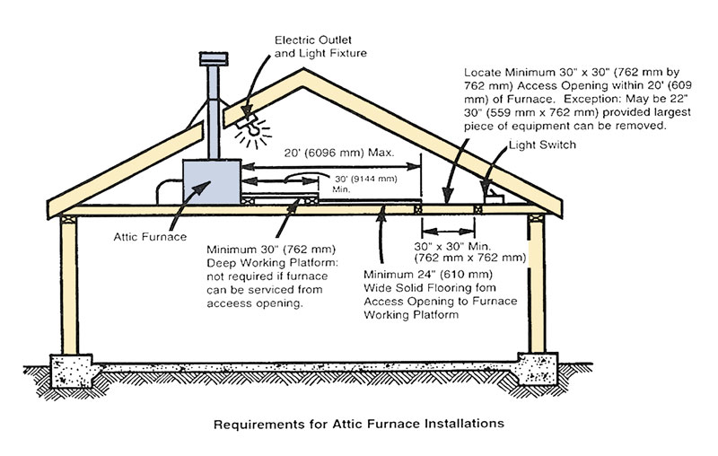
508.0 Appliances on Roofs, in Attics or Under‐Floor Spaces.
“We’ve always had provisions for appliances on a roof with regard to how far away it can be, travel distance, how big an opening it needs to have, an illuminating fixture — all of that stuff — but we never worried about it in attics or under-floor spaces,” he said. “Now if you have your appliances in an attic or under-floor space, you have to apply the same rules as you would for one on the roof.”
509.2.6 Direct‐Vent Appliances. Listed direct vent appliances shall be installed in accordance with the manufacturer’s installation instructions. [NFPA 54:12.3.5.1]
509.2.6.1 Through‐the‐Wall Vent Termination. Through‐the‐wall vent terminations for listed direct‐vent appliances shall be in accordance with Section 509.8.1. [NFPA 54:12.3.5.2]
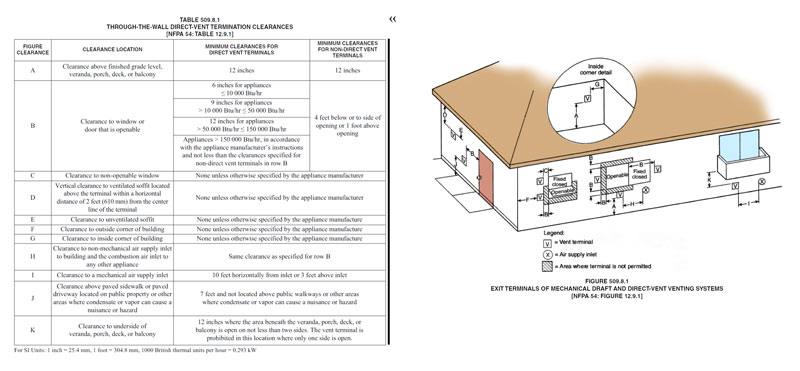
509.8 Through‐the‐Wall Vent Termination. Through‐the‐wall vent termination shall be in accordance with Section 509.8.1 through Section 509.8.3.
509.8.1 Clearance for Through‐the‐Wall Vent Termination. The clearance for through‐the‐ wall direct and non‐direct vent terminals shall be in accordance with Table 509.8.1 and Figure 509.8.1.
Exception: The clearances in Table 509.8.1 shall not apply to the combustion air intake of a direct vent appliance. [NFPA 54:12.9.1]
“We’re only talking about the exhaust, we’re not talking about the combustion air,” Hamner said. “This is good because you always get these calls: ‘Where can I put it?’ ‘Where does the manufacturer say?’ So, now we have it in the code.”
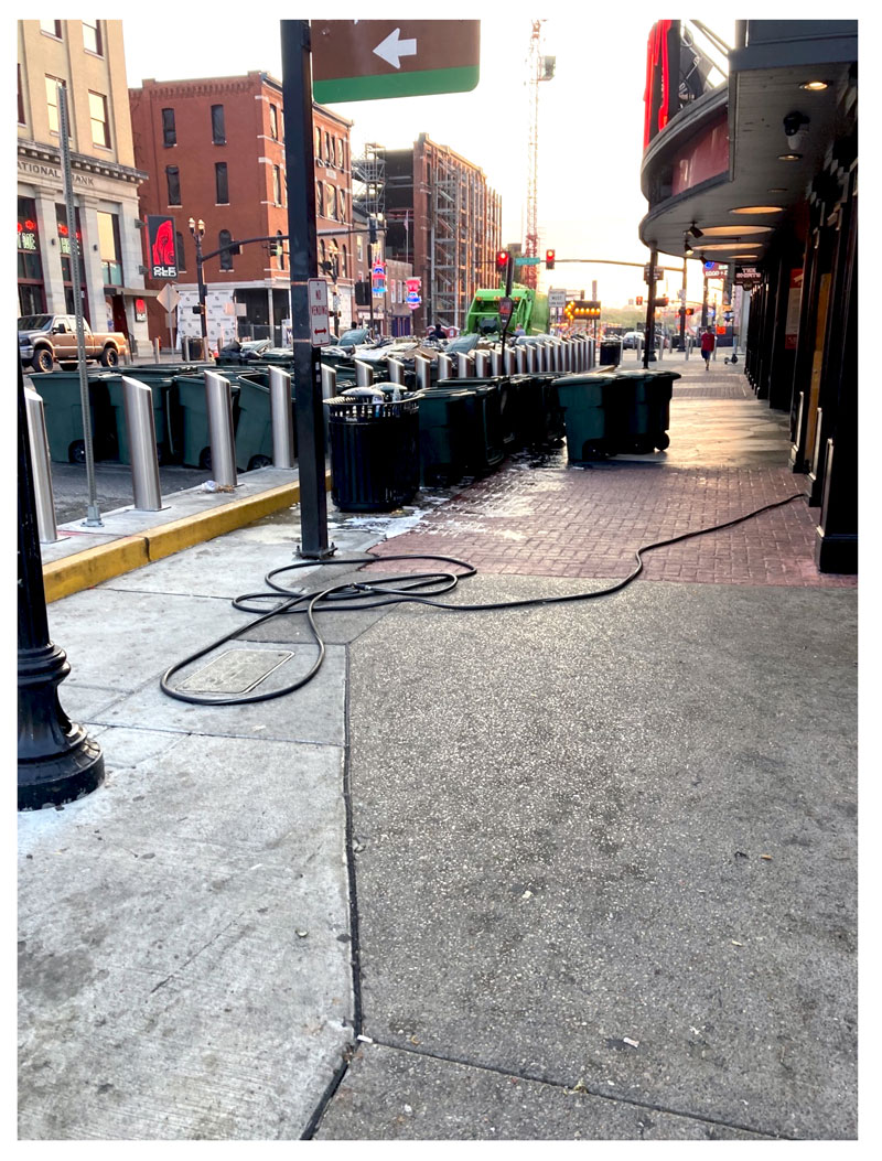
603.5.19 Garbage Can Washers. Where garbage can washers are connected to a potable water supply system, the connection shall be protected against backflow in accordance with Table 603.2.
“In July, I was in Nashville and came across this,” Hamner said, displaying a photo of garbage cans waiting to be sprayed clean. “We hope that this garden hose has some type of backflow prevention.”
603.5.22 Chemical Dispensers. The water supply to chemical dispensers shall be protected against backflowby one of the following:
(1) The chemical dispenser shall comply with ANSI/CAN/ASSE/IAPMO 1055. Where an installation involves a water source coming from a faucet with an integrated vacuum breaker device, a pressure bleed device conforming to IAPMO PS 104 shall be used to protect the vacuum breaker device.
“When does a chemical dispenser typically get installed in new construction?” Hamner asked. “After inspection, right? These get put in after we leave because they’re using a owner-provided fixture.”
606.5.1 Manifolds. Field installed manifolds for water distribution shall conform with the applicable requirements for valves, pipes, and fittings as referenced in this code. Manufactured water distribution manifolds shall be in accordance with IAPMO IGC 109.
“Obviously, when we’re out in the field if you want to build a manifold for a potable water system, we want to make sure all the components are code compliant,” he said.
“If not and we buy a manifold, the manifold has to be listed to this IAPMO standard so we know it’s been tested for potable water.”
609.8.3 Hot‐Water Recirculating Pumps. For healthcare facilities, long term care facilities, hotels, or motels, devices that automatically turn off the recirculation pump(s) shall not be required.
“They can put shutoffs on everything except these. Why?” Hamner asked. “This is healthcare, right? Where we have people who are sick. You want to keep water moving so it’s not stagnant and we mitigate the possibility of bacteria growing in the piping system.”
710.9 Alarm. Such sumps and receiving tanks shall be automatically discharged and, wherein a “public use” occupancy, shall be provided with dual pumps or ejectors arranged to function alternately in normal use and independently. Such pumps shall be capable of running continuously in case of overload or mechanical failure of one of the pumps or ejectors. The pumps shall have an audio and visual alarm, readily accessible, that signals pump failure or an overload condition. The lowest inlet shall have a clearance of not less than 2 inches (51 mm) from the high‐water or “starting” level of the sump.
“We have to make sure the two pumps installed in public use settings can run constantly in an emergency type situation,” Hamner said.
715.3 Existing Sewers. Where permitted by the Authority Having Jurisdiction, trenchless methods of rehabilitation of existing building sewer and building storm sewers shall be installed in accordance with Section 715.3.1 or Section 715.3.2.
715.3.1 Sewer Pipe Lining. For trenchless installation of resin‐impregnated flexible tubing to line existing building sewers and building storm sewers installation shall be in accordance with ASTM F1216, ASTM F2561, ASTM F2599, or ASTM F3240.
“If we’re doing sewer pipe lining, they’ve got to do it per one of those standards,” Hamner said.
715.3.2 Sewer Pipe Replacement. For trenchless installation of polyethylene (PE) pipe using the pipe bursting method to replace existing building sewers and building storm sewers materials shall be in accordance with ASTM F714.
“How many people are open cut trenching anymore to replace sewer lines?” he asked. “Not very many, right? What I see mainly in my area, they’re doing a lot of pipe bursting with poly.”
814.4 Appliance Condensate Drains.
Condensate drain lines from individual condensing appliances shall be sized as required by the manufacturer’s instructions. Condensate drain lines serving more than one appliance connecting to a common indirect waste pipe shall have the connections to the indirect waste pipe protected by a sanitary waste valve complying with ASME A112.18.8, condensate trap complying with IAPMO IGC 196, or trap with a trap primer.
“This is so when we do, say, a hotel, you’ve got air conditioners outside the unit and they want to combine all the condesate drains and take them to one disposal spot,” Hamner said.

906.7 Frost or Snow Closure. Where frost or snow closure is likely to occur in locations having minimum design temperature below 0°F (‐17.8°C), vent terminals shall be not less than 3 inches (76 mm) in diameter, but in no event smaller than the required vent pipe. The change in diameter shall be made inside the building not less than 1 foot (305 mm) below the roof in an insulated space and terminate not less than 10 inches (254 mm) above the roof, or in accordance with the Authority Having Jurisdiction.
“I started plumbing in 1996 and we’ve been doing this since I started plumbing,” Hamner said. “Our vent terminations are no less than three inches. Yes, this helps. It’s a good fix, but it doesn’t solve everything.”
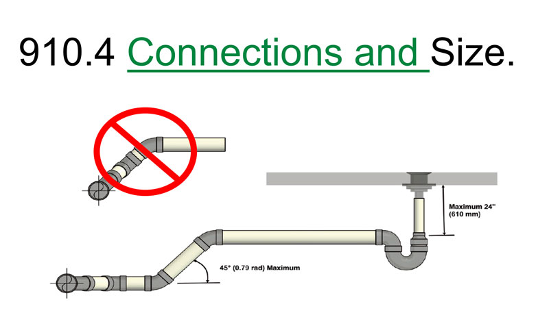
910.4 Connections and Size. Branches serving traps shall connect to the main line at an angle not exceeding 2 percent. Each waste pipe and each trap in such a system shall be not less than two pipe sizes exceeding the sizes required by Chapter 7 of this code, and not less than two pipe sizes exceeding a fixture tailpiece or connection.
“What this is telling you, you can do it anywhere in what you want to call the trap arm, but not after the connection to the main,” Hamner said.
911.0 Circuit Venting.
911.1 Circuit Vent Permitted. A maximum of eight flooroutlet water closets, showers, bathtubs, or floor drains connected to a horizontal branch shall be permitted to be circuit vented. Each trap arm shall connect horizontally to the horizontal branch being circuit vented in accordance with Table 1002.2. The horizontal branch shall be classified as a drain and a vent from the most downstream trap arm connection to the most upstream trap arm connection to the horizontal branch.
Exception: Back‐outlet and wall‐hung water closets shall be permitted to be circuit vented provided that no floor outlet fixtures are connected to the same horizontal branch. Backoutlet and wall‐hung water closets shall connect horizontally to the horizontal circuit vented drain.
“What that’s saying is when we have our backoutlet water closets, we’re not going to come into the back-outlet water closet and go down into the circuit vent,” he said.
“We need to bring our circut vent up to the level.”
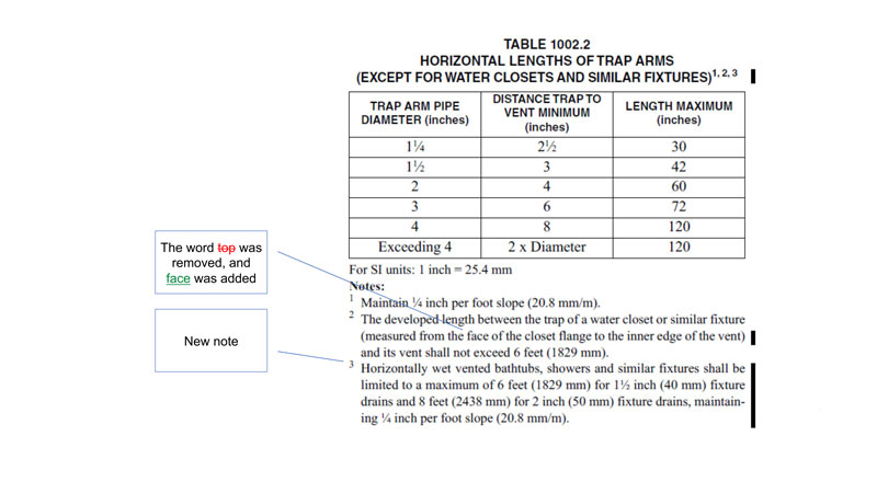
TABLE 1002.2
HORIZONTAL LENGTHS OF TRAP ARMS (EXCEPT FOR WATER CLOSETS AND SIMILAR FIXTURES) 1, 2, 3
For SI units: 1 inch = 25.4 mm
Notes:
1 Maintain 1⁄4 inch per foot slope (20.8 mm/m).
2 The developed length between the trap of a water closet or similar fixture (measured from the face of the closet flange to the inner edge of the vent) and its vent shall not exceed 6 feet (1829 mm).
3 Horizontally wet vented bathtubs, showers and similar fixtures shall be limited to a maximum of 6 feet (1829 mm) for 1½ inch (40 mm) fixture drains and 8 feet (2438 mm) for 2 inch (50 mm) fixture drains, maintaining ¼ inch per foot slope (20.8 mm/m).
“The main thing is we talked about how our trap arm lengths slope and the opening of our vents go below the trap,” he said. “We really don’t have that problem when we’re doing horizontal wet venting. I like this change. You don’t have this roundabout piping going on. We’re not putting our wye in for a water closet and getting within three feet or whatever of our fixture and then wrapping back around to our lavatory.”
1101.13.1 Rain Leaders and Conductors. Rain leaders and conductors connected to a building storm sewer shall have a cleanout installed at the base of the outside leader or conductor before it connects to the horizontal drain.
“On storm leaders, at the base we’re always going to have a cleanout, whether it be inside or outside the building,” Hamner said.
Hamner explained that Chapter 12 has been revised to correlate with NFPA 54-2021 and Chapter 13 to correlate with NFPA 99-2021 in accordance with IAPMO’s Regulations Governing Committee Projects. There are no changes to Chapter 14.
1505.5 Water Pressure. Reclaimed (recycled) water systems supplying water to water closets, urinals, and trap primers shall be capable of delivering not less than 15 pounds‐ force per square inch (psi) (103 kPa) residual pressure at the highest and most remote outlet served. Where the water pressure in the reclaimed water supply system within the building exceeds 80 psi (552 kPa), a pressure reducing valve reducing the pressure to 80 psi (552 kPa) or less to water outlets in the building shall be installed.
“We have these recycled or reclaimed water systems serving the water closets and urinals, but we never had any regulation on how much pressure,” Hamner said. “So, this just kind of aligns with what Chapter 6 says to do with these systems.”
1506.5 Water Pressure. On‐site treated non‐ potable water systems supplying water to water closets, urinals, and trap primers shall be capable of delivering not less than 15 pounds‐force per square inch (psi) (103 kPa) residual pressure at the highest and most remote outlet served. Where the water pressure in the on‐site treated non‐potable water supply system within the building exceeds 80 psi (552 kPa), a pressure reducing valve reducing the pressure to 80 psi (552 kPa) or less to water outlets in the building shall be installed.
“Same thing on the on-site treated non-potable water systems,” he said. “You’ve got to protect the fixtures and make sure they work correctly.”
1603.20 Rainwater Diversion Valves. Rainwater diversion valves ranging from 2 inches (50 mm) through 4 inches (100 mm) in diameter shall comply with IAPMO PS 59. Rainwater diversion valves ranging from 6 inches (150 mm) to 12 inches (300 mm) in diameter shall comply with IAPMO IGC 352. Valves shall be accessible and include a filter located upstream of the valve when required.
With that, Hamner concluded his presentation.
“Thank you all for attending,” he said. “If you have any questions or want training brought to you from IAPMO, contact the IAPMO Training and Certification team at seminars@iapmo.org.”

Geoff Bilau
Last modified: March 20, 2024