September 19, 2024

From the 2024 UPC Illustrated Training Manual, Chapter 6 – WATER SUPPLY AND DISTRIBUTION
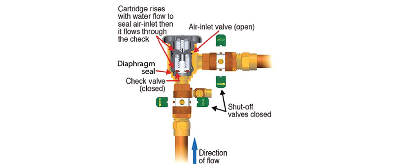
603.3.6 Spill-Resistant Pressure Vacuum Breaker (SVB). A pressure-type vacuum breaker backflow prevention assembly consists of one check valve force loaded closed and an air inlet vent valve force loaded open to atmosphere, positioned downstream of the check valve and located between and including two tightly closing shutoff valves and test cocks.
The spill-resistant type vacuum breaker (SVB) is essentially a next-generation PVB. This assembly evolved because of the spillage encountered with the PVB. The function of the SVB is to eliminate the water spillage of the PVB.
The pressure vacuum breaker requires that both the check valve and air inlet act independently, but the components of the SVB are not required to be independent of each other. During operation (flow), the diaphragm at the bottom of the valve chamber allows the poppet to close before the internal check valve opens, preventing most of the spillage that normally occurs with a PVB. In this way, the air inlet can be closed as the check is closed again, eliminating the spill (see Figure 603.3.6).
The SVB provides the same type of protection as the PVB and can only be used where the PVB can be used.

SPILL RESISTANT PRESSURE VACUUM BREAKER
From the 2024 UMC Illustrated Training Manual, Chapter 5 – EXHAUST SYSTEMS
510.5.2 Factory-Built Grease Ducts. Factory-built grease ducts listed in accordance with UL 1978 shall be permitted to use materials in accordance with their listing. {NFPA 96:7.5.1.2}
510.5.3 Installation. All seams, joints, penetrations, and duct-to-hood collar connections shall have a liquid-tight continuous external weld. [NFPA 96:7.5.2.1]
Because visual verification is important, many jurisdictions require the installer to provide a light and extension cord to internally illuminate welded seams for liquidtight joint inspection.
Exceptions:
(1) Factory-built grease ducts listed in accordance with UL 1978 shall be permitted to incorporate nonwelded joint construction in accordance with their listings. {NFPA 96:7.5.2.1.1}
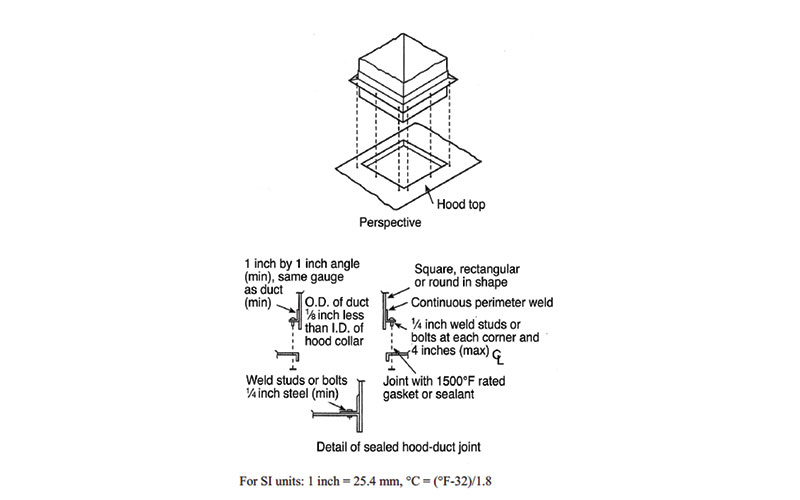
(2) Duct-to-hood collar connections as shown in Figure 510.5.3 shall not require a liquidtight continuous external weld. [NFPA 96:7.5.2.2]
(3) Penetrations shall be permitted to be sealed by other listed devices that are tested to be greasetight and are evaluated under the same conditions of fire severity as the hood or enclosure of listed grease extractors and whose presence does not detract from the hood’s or duct’s structural integrity. [NFPA 96:7.5.2.3]
(4) Internal welding shall be permitted, provided the joint is formed or ground smooth and is readily accessible for inspection. [NFPA 96:7.5.2.4]
Figure 510.5.3 details a portion of the hood that needs to be turned down and a 1-inch by 1-inch angle spaced above the bottom of the duct. This overlapping material in the hood will protect the sealant or gasket used at the duct connection from exposure to grease, cleaning agents and fire.

PERMITTED DUCT-TO HOOD COLLAR CONNECTION
[NFPA 96: FIGURE 7.5.2.2]
(This is not to be considered the official position of IAPMO, nor is it an official interpretation of the Codes.)

IAPMO
IAPMO develops and publishes the Uniform Plumbing Code®,the most widely recognized code of practice used by the plumbing industry worldwide; Uniform Mechanical Code®; Uniform Swimming Pool, Spa and Hot Tub Code®; and Uniform Solar Energy, Hydronics and Geothermal Code™ — the only plumbing, mechanical, solar energy and swimming pool codes designated by ANSI as American National Standards — and the Water Efficiency Standard (WE-Stand)™. IAPMO works with government, contractors, labor force, and manufacturers to produce product standards, technical manuals, personnel certification/educational programs and additional resources in order to meet the ever-evolving demands of the industry in protecting public health and safety.
Last modified: October 10, 2024
