September 12, 2024

From the 2024 UPC Illustrated Training Manual, Chapter 6 – WATER SUPPLY AND DISTRIBUTION
609.11.1 Mechanical Devices. Where listed mechanical devices are used, the manufacturer’s specifications as to location and method of installation shall be followed.
Although water hammer is a subject usually left up to plumbing engineers, the effects of water hammer must be dealt with every day by plumbing contractors everywhere. Water hammer is easily recognized by the banging or thumping noise that is heard when valves are shut off. Although this is an easy way to recognize the problem, water hammer does not always make these telltale noises. Water hammer occurs when the flow of moving water is suddenly stopped by a closing valve. This sudden stop results in a tremendous spike of pressure behind the valve, which acts like a tiny explosion inside the pipe. This pressure spike reverberates throughout the plumbing system, rattling and shaking pipes, until it is absorbed. Normally, a sufficient pocket of air will absorb such a pressure spike, but if no pocket of air is present, expensive fixtures and appliances within the plumbing system will be damaged as they are left to absorb this pressure spike.
It used to be thought that an air chamber, or capped stand pipe, was an effective solution to controlling water hammer. However, within an air chamber, nothing separates the air from the water. It only takes a few short weeks before the air is absorbed into the water, leaving the air chamber waterlogged and completely ineffective against water hammer. Laboratory tests confirm that the air is depleted by simple air permeation and by interaction between static pressure and flow pressure. In the diagram shown in Figure 609.11.1a, notice the difference in water level between “Static Line Pressure” and “Postcycle Static Level.” One can easily see that this method of protecting against water hammer is ineffective.
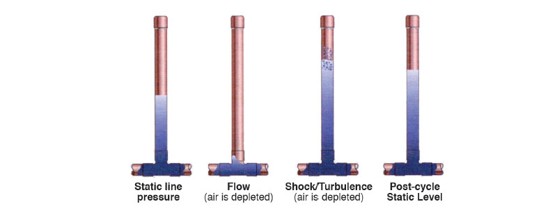
CHAMBER AIR CUSHION DEPLETION
The most effective means of controlling water hammer is a measured, compressible cushion of air which is permanently separated from the water system. The arrester model shown in Figure 609.11.1b employs a pressurized cushion of air and a two O-ring piston, which permanently separates this air cushion from the water system. When the valve closes and the water flow is suddenly stopped, the pressure spike pushes the piston up the arrester chamber against the pressurized cushion of air. The air cushion in the arrester reacts instantly, absorbing the pressure spike that causes water hammer.
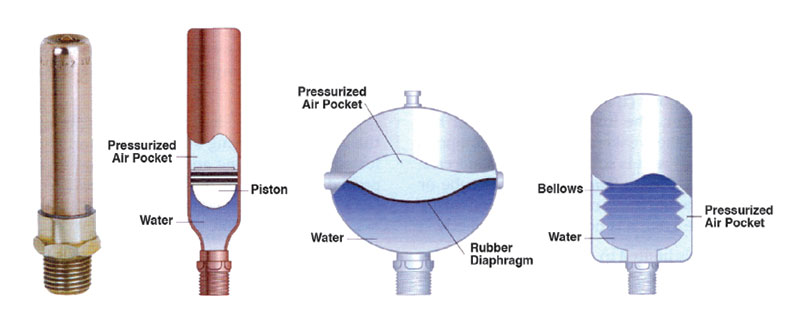
TYPES OF WATER HAMMER ARRESTERS
Many other styles of water hammer arresters are manufactured. There are residential installation models and industrial models that are also represented in Figure 609.11.1b. Always consult the manufacturer’s installation and product manuals for the proper size and installation location for a water hammer arrester.
From the 2024 UMC Illustrated Training Manual, Chapter 8 – CHIMNEYS AND VENTS
802.4.3 Special Gas Vents. Special gas vents shall be listed and labeled in accordance with UL 1738 and installed in accordance with the special gas vent manufacturer’s installation instructions. [NFPA 54:12.5.4]
All special gas vents are listed vent materials. Special gas vents are listed in accordance with UL 1738, Standard for Venting Systems for Gas-Burning Appliances, Categories II, III and IV. See Figure 802.4.3a. Installation instructions for special gas vents include limitations on operating temperature, categories of appliance to be used with each vent, clearance to combustible materials, types of fittings and joint sealant to be used and vent termination requirements.
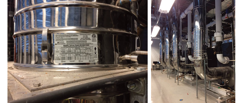
RIGHT: FIGURE 802.4.3B, VENT SUPPORTS
Special attention should be given to the following areas:
1. Proper support for the special vent to prevent sagging and to allow for expansion, contraction and condensate drainage. See Figure 802.4.3b.
2. Proper cutting and cleaning of joints and fittings, and the use of recommended joint sealants (substitutes are not usually permitted).
3. Construction of a condensate trap (see appliance manufacturer’s instruction for special requirements).
4. Wall penetrations (the pipe should not be secured at a thimble, as the pipe must be allowed to move to accommodate expansion and contraction).
5. Insulation [the vent pipe or the fittings of the inside of a wall thimble must not be insulated when polymeric (nonmetallic) vent materials are used].
(This is not to be considered the official position of IAPMO, nor is it an official interpretation of the Codes.)

IAPMO
IAPMO develops and publishes the Uniform Plumbing Code®,the most widely recognized code of practice used by the plumbing industry worldwide; Uniform Mechanical Code®; Uniform Swimming Pool, Spa and Hot Tub Code®; and Uniform Solar Energy, Hydronics and Geothermal Code™ — the only plumbing, mechanical, solar energy and swimming pool codes designated by ANSI as American National Standards — and the Water Efficiency Standard (WE-Stand)™. IAPMO works with government, contractors, labor force, and manufacturers to produce product standards, technical manuals, personnel certification/educational programs and additional resources in order to meet the ever-evolving demands of the industry in protecting public health and safety.
Last modified: October 10, 2024
