November 20, 2025

From the 2024 UPC Illustrated Training Manual, Chapter 9, VENTS
908.2.2 Size. The wet vent shall be sized based on the fixture unit discharge into the wet vent. The wet vent shall be not less than 2 inches (50 mm) in diameter for 4 drainage fixture units (dfu) or less, and not less than 3 inches (80 mm) in diameter for 5 dfu or more. The dry vent shall be sized in accordance with Table 702.1 and Table 703.2 based on the total fixture units discharging into the wet vent.
In order to prevent excessive interference at the junction of the lateral connections, the sizing requirements for the horizontal wet vent branch are more restrictive than what is allowed in Table 703.2. If combined flows at the junctions are excessive, then local flooding or large pneumatic pressure fluctuations may occur. Therefore, the minimum size for the horizontal wet vent pipe is two inches and limited to four fixture units. A system having five or more fixture units must be increased to three inches. The reduced fixture units limit the practical flow capacity allowing the drain sufficient volume for continuous air space above the flow. Along with sufficient volume within the pipe, it is also critical to maintain a minimum uniform slope of 1/4-inch per foot to prevent surges of water to crest the crown of the pipe (see Section 708.1).
From the 2024 UMC Illustrated Training Manual, Chapter 5, EXHAUST SYSTEMS
503.2 Fans. Parts of fans in contact with explosive or flammable vapors, fumes, or dusts shall be of nonferrous or nonsparking materials, or their casing shall be lined or constructed of such material. Where the size and hardness of materials passing through a fan are capable of producing a spark, both the fan, and the casing shall be of nonsparking materials. Where fans are required to be spark-resistant, their bearings shall not be within the airstream, and parts of the fan shall be grounded. Fans in systems handling materials that are likely to clog the blades, and fans in buffing or woodworking exhaust systems, shall be of the radial-blade or tube-axial type.
Equipment used to exhaust explosive or flammable vapors, fumes, or dusts shall bear an identification plate stating the ventilation rate for which the system was designed.
Fans located in systems conveying corrosives shall be of materials that are resistant to the corrosive or shall be coated with corrosion-resistant materials.
Either all parts of fans in contact with explosive or flammable vapors, fumes or dusts must be made of nonferrous or non-sparking materials or their casing must be constructed or lined with such materials. However, when the size and hardness of any material passing through the fan(s) are capable of producing a spark, both the fan and the casing must be made from non-sparking materials. When spark resistant fans are required, their bearings must be outside the air stream carrying explosive or flammable vapors. In addition, all fan parts must be electrically grounded. These safety precautions limit the likelihood of sparking that can ignite the flammable vapors or dusts. Such special-purpose fans should be listed for their intended use by an approved agency.
For the following applications, fans must be of the radialblade or tube-axial type (see Figure 503.2).
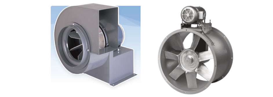
RADIAL FAN AND TUBE AXIAL FAN
- To handle materials likely to clog the blades (metals, wet or heavy dusts); and
- For buffing or woodworking systems.
Equipment used to exhaust explosive or flammable vapors, fumes or dusts must bear an identification plate showing the ventilation in cubic feet per minute (cfm) for which the system was designed.
Fans located in a product-conveying duct system containing corrosive vapors must be built from, or coated thoroughly with, corrosion-resistant materials. The manufacturer of the fan and the listing agency should verify that the chosen fan is acceptable for the particular corrosive vapor to be vented. Each corrosive vapor has its own properties; therefore, no single fan material can possess universal application for all types of vapors.
Not all fans can operate effectively under high resistance. Duct velocities required in Table 505.9 dictate the maximum size of a duct system needed to maintain that velocity. Long duct systems increase the total static resistance that the fan needs to overcome. Simply spinning a fan faster may not achieve the required result of more airflow. Designing a fan and motor capable of moving product-laden air within a duct system is critical to the overall operation of the product conveying and removal system.
(This is not to be considered the official position of IAPMO, nor is it an official interpretation of the Codes.)

IAPMO
IAPMO develops and publishes the Uniform Plumbing Code®,the most widely recognized code of practice used by the plumbing industry worldwide; Uniform Mechanical Code®; Uniform Swimming Pool, Spa and Hot Tub Code®; and Uniform Solar Energy, Hydronics and Geothermal Code™ — the only plumbing, mechanical, solar energy and swimming pool codes designated by ANSI as American National Standards — and the Water Efficiency Standard (WE-Stand)™. IAPMO works with government, contractors, labor force, and manufacturers to produce product standards, technical manuals, personnel certification/educational programs and additional resources in order to meet the ever-evolving demands of the industry in protecting public health and safety.
Last modified: November 20, 2025