June 5, 2025
From the 2024 UPC Illustrated Training Manual, Chapter 3, GENERAL REGULATIONS
310.4 Use of Vent and Waste Pipes. Except as hereinafter provided in Section 908.0 through Section 911.0, no vent pipe shall be used as a soil or waste pipe, nor shall a soil or waste pipe be used as a vent. Also, single-stack drainage and venting systems with unvented branch lines are prohibited.
The UPC’s basic principle for waste and vent is that the two shall never comingle. In other words, the vent pipe shall never be used for draining a fixture, and the drain pipe shall never be used for venting a fixture. There are four basic exceptions to this principle. Sections 908.0 Wet Venting, 909.0 Special Venting for Island Fixtures, 910.0 Combination Waste and Vent Systems, and 911.0 Circuit Venting in Chapter 9 discuss “special” venting systems that utilize different configurations and requirements, such as increased sizes and placement of fittings to accommodate venting. See Chapter 9 for explanations and illustrations. See Figure 310.4a for an example of incorrect use of a second floor vertical waste pipe for a first floor vent pipe.
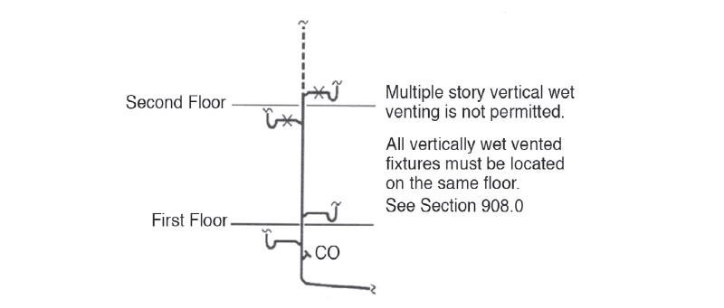
INCORRECT USE OF VENT
Single-stack systems, such as the Philadelphia Stack System and the Sovent System, utilize one vertical stack for both sanitary waste and venting. Branches connecting to these systems carry waste from fixtures that are not individually vented. The design of these systems (fixtures without individual trap vents) does not meet the requirements of the code and therefore they are prohibited.
Single-stack systems such as those mentioned above have been used in the United States and around the world. The code recognizes this fact by placing a method of singlestack venting in Appendix C. The system must be designed by an engineering professional and approved by the AHJ. Other methods may be used but must adhere to the requirements of Sections 301.3 and 301.5. See Figure 310.4b for an example of one type of single-stack venting system.
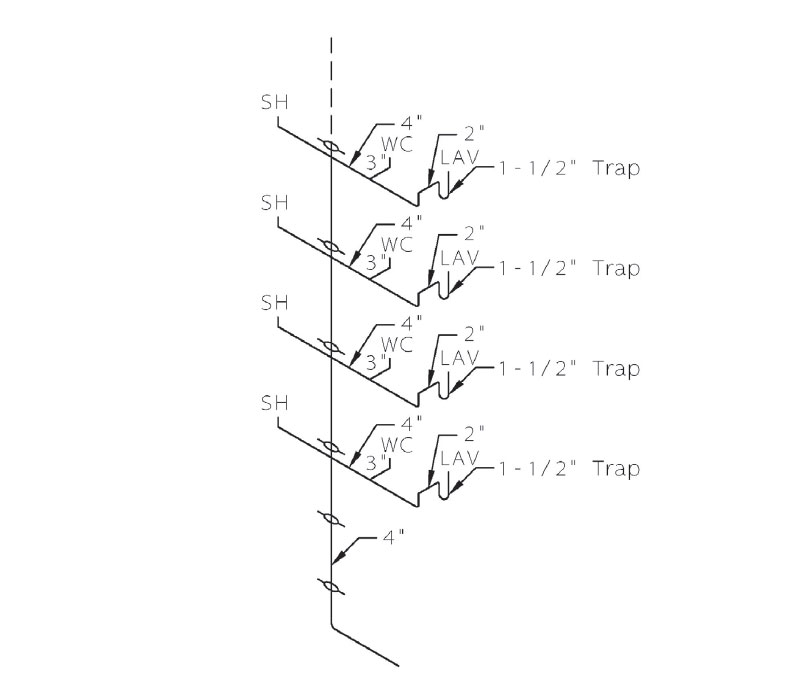
AN ALTERNATE ENGINEERED SINGLE-STACK DRAINAGE SYSTEM (FROM ILLUSTRATED PLUMBING CODES DESIGN HANDBOOK, ASPE)
From the 2024 UMC Illustrated Training Manual, Chapter 5, EXHAUST SYSTEMS
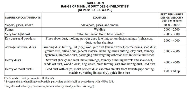
505.9 Minimum Velocities and Circulation. The velocity and circulation of air in work areas shall be such that contaminant’s are captured by an airstream at the area where the emissions are generated and conveyed into a product-conveying duct system. Mixtures within work areas where contaminants are generated shall be diluted to be accordance with Section 505.3 with air that does not contain other contaminants. The velocity of air within the duct shall be not less than set forth in Table 505.9.
Systems conveying particulate matter shall be designed by employing the constant velocity method. Systems conveying explosive or radioactive materials shall be prebalanced through duct sizing. Other systems shall be permitted to be designed with balancing devices such as dampers. Dampers provided to balance airflow shall be provided with securely fixed minimum-position blocking devices to prevent restricting flow below the required volume or velocity.
In conveying solid particulates, vapors or noxious, corrosive, flammable or explosive gases, adequate velocity must be maintained throughout the system. Otherwise, many contaminants will tend to precipitate, condense and separate from the air stream; if this occurs, the deposit will block the duct system. Mixtures within the work area must be diluted below 25 percent of their LFL with air that does not contain other contaminants. Minimum velocities are set forth in Table 505.9 for various common industrial materials.
The entire work area ventilation system must be designed and constructed so that contaminants are captured by an air stream at the area of generation (typically a single workstation) and conveyed directly into the product-conveying duct system.
Systems for particulate matter are to be designed using the Constant Velocity Method. Common duct sizes limit the ability to maintain constant velocity. Certain systems allow openings intended to maintain minimum velocities in larger ducts without causing excessive velocities in smaller attached ducts (see Figure 505.9). Systems conveying explosive or radioactive materials are to be pre-balanced through duct sizing. Other systems may be designed with balancing devices such as dampers, provided that minimum position blocking devices are installed to prevent restricting flow below the minimum required volume or velocity.
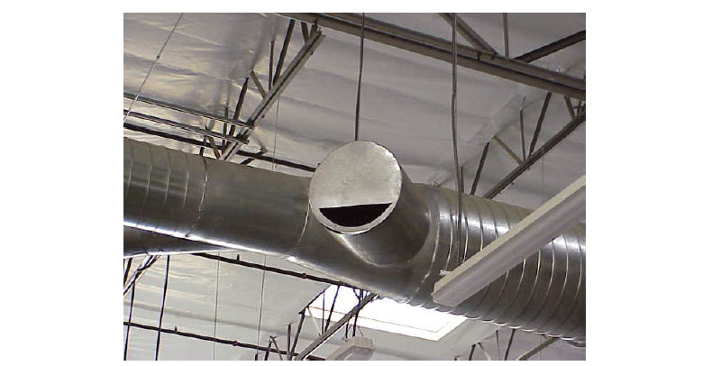
OPENING USED TO MAINTAIN A CONSTANT VELOCITY
While the duct system can be designed and installed with predictable results, humidity and temperatures within the industrial plant can be difficult to control or predict. Large openings, such as windows, doors or vents, can drastically alter the environment. Similarly, subsequent remodeling of the structure or the heating, ventilation and air-conditioning (HVAC) system may affect the product-conveying system and are difficult to predict. Care should be taken when reviewing proposed remodeling or alterations to these installations so that the existing exhaust systems are not adversely impacted.
A common question posed by those who design product conveying duct systems is whether a small cyclone-type dust collector or self-contained or portable mechanical dust-collection system can be used to collect flammable dusts in bags or containers at each piece of woodworking equipment, in lieu of the central system required by the building code of the jurisdiction. The bag acts as a filter. The smallest of the particles pass through the bag and settle on horizontal surfaces, thereby increasing the risk of ignition and combustion. Since storage of wood residues should be in exterior noncombustible containers or in other approved locations as specified in the building code of the jurisdiction, a central product-conveying duct system that will transport hazardous dusts to the outside of the building is required.
Note that under Section 506.6 ducts conveying explosive dust must have explosion vents located outside the building.
(This is not to be considered the official position of IAPMO, nor is it an official interpretation of the Codes.)
IAPMO
IAPMO develops and publishes the Uniform Plumbing Code®,the most widely recognized code of practice used by the plumbing industry worldwide; Uniform Mechanical Code®; Uniform Swimming Pool, Spa and Hot Tub Code®; and Uniform Solar Energy, Hydronics and Geothermal Code™ — the only plumbing, mechanical, solar energy and swimming pool codes designated by ANSI as American National Standards — and the Water Efficiency Standard (WE-Stand)™. IAPMO works with government, contractors, labor force, and manufacturers to produce product standards, technical manuals, personnel certification/educational programs and additional resources in order to meet the ever-evolving demands of the industry in protecting public health and safety.
Last modified: June 5, 2025