June 27, 2024

From the 2024 UPC Illustrated Training Manual, Chapter 12 – FUEL GAS PIPING
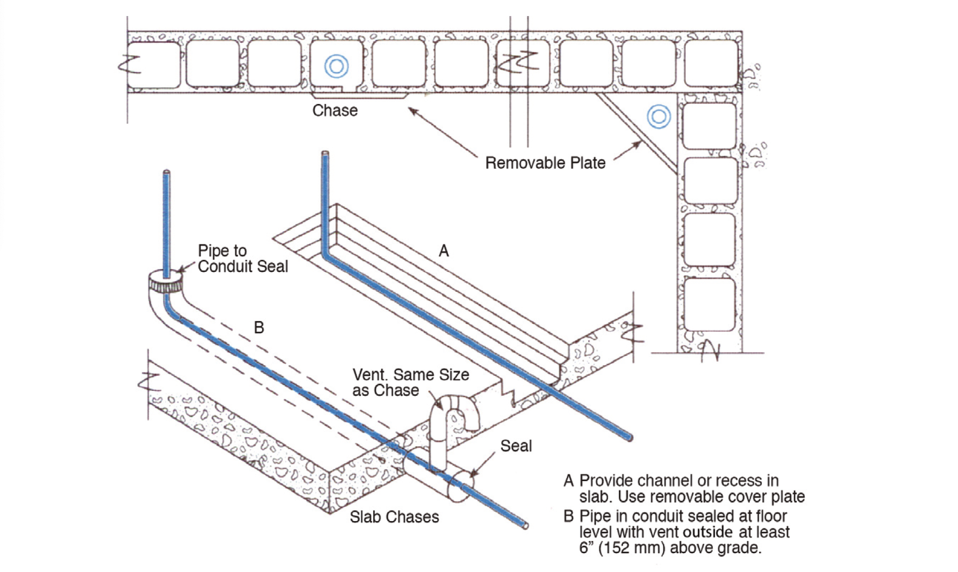
1210.1.6 Piping Underground Beneath Buildings. Where gas piping is installed underground beneath buildings, the piping shall be either of the following:
(1) Encased in an approved conduit designed to withstand the imposed loads and installed in accordance with Section 1210.1.6.1 or Section 1210.1.6.2.
(2) A piping/encasement system listed for installation beneath buildings. [NFPA 54:7.1.6]
Gas leaks in underground piping can migrate along the trench and into the building instead of venting to the atmosphere above grade. This condition can be extremely hazardous. In some areas, there is also a requirement that the installation should be made so that the piping can be removed or replaced without removal of the flooring materials. The requirement to seal the casing against water entry is in keeping with the desire to exercise good workmanship. See Figure 1210.1.6 for an illustration of a below-grade foundation wall penetration.

GAS PIPING FLOOR INSTALLATIONS
From the 2024 UMC Illustrated Training Manual, Chapter 7 – COMBUSTION AIR
701.10 Louvers, Grilles, and Screens. The required size of openings for combustion, ventilation, and dilution air shall be based on the net free area of each opening. Where the free area through a design of louver, grille, or screen is known, it shall be used in calculating the size opening required to provide the free area specified. Where the louver and grille design and free area are not known, it shall be assumed that wood louvers have 25 percent free area and metal louvers and grilles have 75 percent free area. Nonmotorized louvers and grilles shall be fixed in the open position. [NFPA 54:9.3.7.1]
Usually, louvers or grilles are installed on combustion air openings. This is to protect the openings against entry of rain, birds or rodents. Excessive amounts of water (rain) could have an adverse effect on the appliance or equipment and birds nesting in the airway could obstruct the combustion air source and could make the air unsanitary. In these cases, the solid portion of the louver or grille must be considered when determining the net free area of the opening. If the free area of the grille is known (some prefabricated grilles are provided with labels indicating the free area), the label is to be used to determine the net free area. If the free area is not known, the overall “gross area” should be measured and a factor of 25 percent should be applied when the grille has wood louvers, and a factor of 75 percent should be applied when the grille has metal louvers to account for the blocking effect of the louvers and to determine the free area. If the opening is covered with a wire mesh, the openings should not be smaller than 1/4 inch, as smaller size mesh is subject to obstruction by the accumulation of dirt or lint.
Example:
A grille has an overall dimension of 30 inches by 25 inches.
If the grille has wood louvers, what is the free area?
Wood grille: 30 x 25 x 0.25 = 187.5 square inches
If the grille has metal louvers, what is the free area?
Metal grille: 30 x 25 x 0.75 = 562.5 square inches
Example:
If 100 square inches of net free opening is required and the
grille has metal louvers (75 percent free area), what size grille
would be required?
100 ÷ 0.75 = 133.3 square inches
Grille size: 10 x 14 = 140 square inches (exceeds minimum)
Manual and fire dampers are prohibited on combustion air openings (see Section 701.12); however, motorized dampers are allowed, provided there is assurance that they will open, and remain open, when the main burners of the appliance are operational. This section requires that the motorized damper be interlocked so the burners will not operate if the damper is closed, and that they will shut down if the damper closes during the equipment operation. As mechanical devices installed on combustion air openings or ducts are subject to failure, this requirement will provide the necessary assurance that the appliance will not operate unless the combustion air is made available.
(This is not to be considered the official position of IAPMO, nor is it an official interpretation of the Codes.)

IAPMO
IAPMO develops and publishes the Uniform Plumbing Code®,the most widely recognized code of practice used by the plumbing industry worldwide; Uniform Mechanical Code®; Uniform Swimming Pool, Spa and Hot Tub Code®; and Uniform Solar Energy, Hydronics and Geothermal Code™ — the only plumbing, mechanical, solar energy and swimming pool codes designated by ANSI as American National Standards — and the Water Efficiency Standard (WE-Stand)™. IAPMO works with government, contractors, labor force, and manufacturers to produce product standards, technical manuals, personnel certification/educational programs and additional resources in order to meet the ever-evolving demands of the industry in protecting public health and safety.
Last modified: June 27, 2024
