June 12, 2025
From the 2024 UPC Illustrated Training Manual, Chapter 9, VENTS
905.3 Vent Pipe Rise. Unless prohibited by structural conditions, each vent shall rise vertically to a point not less than 6 inches (152 mm) above the flood-level rim of the fixture served before offsetting horizontally, and where two or more vent pipes converge, each such vent pipe shall rise to a point not less than 6 inches (152 mm) in height above the flood-level rim of the plumbing fixture it serves before being connected to any other vent. Vents less than 6 inches (152 mm) above the flood-level rim of the fixture shall be installed with approved drainage fittings, material, and grade to the drain.
The ideal installation for a plumbing fixture would be a vertical fixture drain connecting with the fixture trap arm by a sanitary tee with the vent rising vertically and connecting with a branch vent or going through the roof. This is defined as a “continuous vent” (see Figure 905.3a). This continuous vent must remain vertical until it is at least six inches above the overflow rim of the fixture. It may then turn horizontally or connect to other vents in the system. This ensures that if there is a stoppage and an overflow condition, the waste from one fixture will not flow into the other fixtures via the vent.
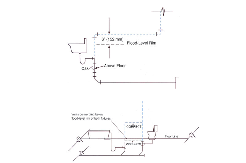
The vent connection is always below the overflow rim of the fixture but normally there is only a short vertical piece that is below the fixture rim; however, this is not always possible. Sometimes there will be obstructions in the structure of the building that will prevent this ideal condition. Significant portions of the vent may have to be installed below the flood-level rim of the fixture. For example, there may be an installation of a floor drain where the distance from a wall that might be used to place the drain’s vent exceeds the trap arm distance. In this installation the vent would have to be placed in a horizontal position until it could turn vertically in the wall (see Figure 905.3b).
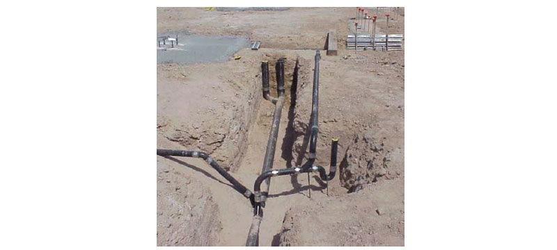
VENT INSTALLED IN HORIZONTAL POSITION
This vent, until it rises 6 inches above the overflow rim of the fixture, is in fact a drain. If there is an overflow condition, the vent would be filled to the rim of the fixture. When the stoppage is cleared, the waste in the vent has to flow to the drain and it must do this using drainage fittings. The horizontal portion of the vent must also be graded back to the drain to allow the overflow effluent to recede.
From the 2024 UMC Illustrated Training Manual, Chapter 13, FUEL GAS PIPING
1308.6.5 Identification. Line pressure regulators at multiple regulator installations shall be marked by a metal tag or other permanent means designating the building or the part of the building being supplied. [NFPA 54:5.7.6]
Gas pressure regulators are designed to maintain constant downstream gas pressure, regardless of change in the gas flow or in the conditions of the upstream pressure. Ideally, they restrict the flow from the inlet pressure side to balance exactly what should be the downstream gas pressure. There are four basic areas where regulators are used:
- A service pressure regulator is installed to reduce the main gas service pressure to the design pressure of the piping system.
- A line gas pressure regulator may be used to reduce the gas piping main pressure to a lower pressure. A typical example would be in a hybrid pressure system – for example, a 2 psi (13.8 kPa) main pressure to an 11-inch water column pressure to the branches serving the appliances
- An appliance regulator may be needed at the inlet to the appliance, which will reduce the branch pressure to the specific working pressure of the appliance.
- There may be a pressure regulator in the appliance itself, which will reduce the outlet pressure to the working pressure within the appliance.
(This is not to be considered the official position of IAPMO, nor is it an official interpretation of the Codes.)
IAPMO
IAPMO develops and publishes the Uniform Plumbing Code®,the most widely recognized code of practice used by the plumbing industry worldwide; Uniform Mechanical Code®; Uniform Swimming Pool, Spa and Hot Tub Code®; and Uniform Solar Energy, Hydronics and Geothermal Code™ — the only plumbing, mechanical, solar energy and swimming pool codes designated by ANSI as American National Standards — and the Water Efficiency Standard (WE-Stand)™. IAPMO works with government, contractors, labor force, and manufacturers to produce product standards, technical manuals, personnel certification/educational programs and additional resources in order to meet the ever-evolving demands of the industry in protecting public health and safety.
Last modified: June 12, 2025