July 25, 2024

From the 2024 UPC Illustrated Training Manual, Chapter 6 – WATER SUPPLY AND DISTRIBUTION
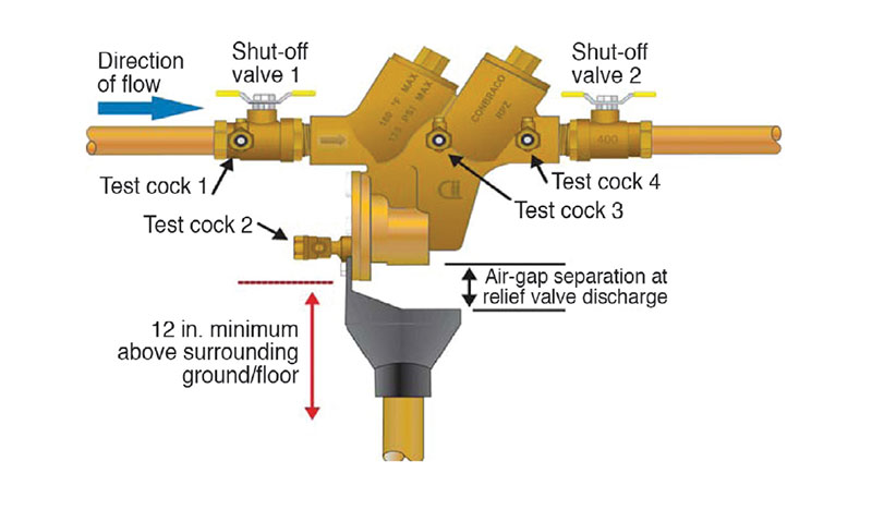
603.3.7 Reduced-Pressure Principle Backflow Prevention Assembly (RP). A reduced-pressure principle backflow prevention assembly consists of two independently acting internally loaded check valves, a differential pressure relief valve, four properly located test cocks, and two isolation valves.
The reduced pressure principle backflow prevention assembly is referred to as the RP, RPPZ, RPZ as well as other acronyms. The RP is the best mechanical backflow preventer available today. It is considered as proper protection for high- or low-hazard applications, backpressure or backsiphonage backflow and containment or isolation protection.
The name of this assembly is derived from a zone of reduced pressure needed for the operation of the relief or vent valve. This device is an assembly of two internally loaded, specially designed and independently operating check valves that have a relief valve installed between the primary valves, specifically designed to maintain a zone of relative differential pressure between the two check valves unless one or both of the check valves are fouled. This assembly has a tightly closing upstream and a tightly closing downstream shutoff valve (see Figure 603.3.7).

REDUCED PRESSURE PRINCIPLE BACKFLOW ASSEMBLY
As water flows through the first check valve, a pressure drop is created. The assembly’s relief valve determines if the supply pressure is greater and will remain closed; if the difference in pressure between the supply and zone is reduced, the relief valve will open. With a loss of supply pressure and both checks closing, the relief valve will open to maintain a minimum pressure of two psi less than the supply pressure of the fluid in the zone and downstream line. If there is a complete loss of supply pressure, the pressure between the two check valves will become atmospheric because the spring has opened the relief valve.
The RP may be used at actual or potential high- or lowhazard applications. As previously mentioned, the assembly provides backpressure and backsiphonage protection.
An RP may be used as meter-service containment protection or on individual fixtures and appliance isolation protection.
A field test of an RP is required on installation, at least annually thereafter, after any repair or when relocated. The assembly must be installed a minimum of 12 inches above the surrounding ground or floor.
An RP’s relief valve has the potential to discharge a significant amount of water. Care should be taken as to its location and provision for indirect drainage. The drainage piping should be sized adequately to take the full discharge of the system. Always refer to the manufacturer’s installation requirements.
From the 2024 UPC Illustrated Training Manual, Chapter 6 – DUCT SYSTEMS
602.2 Combustibles Within Ducts or Plenums. Materials exposed within ducts or plenums shall be noncombustible or shall have a flame spread index not to exceed 25 and a smoke-developed index not to exceed 50, where tested as a composite product in accordance with ASTM E84 or UL 723. Plastic piping installed in plenums shall be tested in accordance with all requirements of ASTM E84 or UL 723. Mounting methods, supports and sample sizes of materials for testing that are not specified in ASTM E84 or UL 723 shall be prohibited.
Exceptions:
(1) Return-air and outside-air ducts, plenums, or concealed spaces that serve a dwelling unit.
(2) Air filters in accordance with the requirements of Section 311.2.
(3) Water evaporation media in an evaporative cooler.
(4) Charcoal filters where protected with an approved fire suppression system.
(5) Products listed and labeled for installation within plenums in accordance with Section 602.2.1 through Section 602.2.4.
(6) Smoke detectors in accordance with the requirements of Section 609.0.
(7) Duct insulation, coverings, and linings and other supplementary materials installed in accordance with Section 605.0.
(8) Materials in a hazardous fabrication area including the areas above and below the fabrication area sharing a common air recirculation path with the fabrication area.
(9) Plastic water distribution piping listed and labeled for use in plenums in accordance with UL 2846 as having a peak optical density not greater than 0.50, an average optical density not greater than 0.15, and a flame spread distance not greater than 5 feet (1524 mm), and installed in accordance with its listing, shall be permitted.
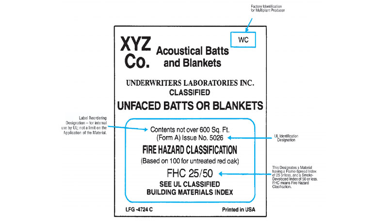
This section requires that materials exposed to the airstream in ducts and plenums exhibit specified surfaceburning characteristics, except in certain locations and products as indicated. The purpose of the requirement is to limit propagation of flames through the duct system or plenum and to limit the quantity of smoke resulting from involvement of insulating and acoustic materials. The method of testing to determine surface-burning characteristics of materials is commonly referred to as the “Steiner Tunnel Test,” as described in ASTM E 84 and (UL 723. The Underwriters Laboratories UL) label indicates only that the material would be suitable based on its flame spread index and smoke developed value. The listing cautions that thermal conductivity, vapor resistance and other properties of the material have not been investigated. Figure 602.2 shows a typical label that is required to be attached to tested materials that comply with the flame spread index and smoke-developed rating required in this section.

TYPICAL LABEL FOR COMBUSTABLE MATERIALS WITHIN DUCTS AND PLENUMS
If ASTM E84 or UL 723 standard test methods are modified and used as a basis to determine flame and smoke ratings, then the tests don’t comply with the standard and the materials may not comply with the required flame and smoke ratings. An inspector or installer seeing ASTM E84 on a pipe would likely assume that it meets the requirement of the code. Simply adding the ASTM E 84 or UL 723 marking to the wall of the pipe does not necessarily mean that the product was tested in full compliance with the standard in the manner that the code intends. Especially for PVC and CPVC pipe, the inspector or installer should examine the material listing and see if the testing agency has modified the testing method and rendered the pipe material noncompliant.
(This is not to be considered the official position of IAPMO, nor is it an official interpretation of the Codes.)

IAPMO
IAPMO develops and publishes the Uniform Plumbing Code®,the most widely recognized code of practice used by the plumbing industry worldwide; Uniform Mechanical Code®; Uniform Swimming Pool, Spa and Hot Tub Code®; and Uniform Solar Energy, Hydronics and Geothermal Code™ — the only plumbing, mechanical, solar energy and swimming pool codes designated by ANSI as American National Standards — and the Water Efficiency Standard (WE-Stand)™. IAPMO works with government, contractors, labor force, and manufacturers to produce product standards, technical manuals, personnel certification/educational programs and additional resources in order to meet the ever-evolving demands of the industry in protecting public health and safety.
Last modified: July 25, 2024
