August 22, 2024

From the 2024 UPC Illustrated Training Manual, Chapter 6 – WATER SUPPLY AND DISTRIBUTION
606.5 Control Valve. A control valve shall be installed immediately ahead of each water-supplied appliance and immediately ahead of each slip joint or appliance supply.
Parallel water distribution systems shall provide a control valve either immediately ahead of each fixture being supplied or installed at the manifold, and shall be identified with the fixture being supplied. Where parallel water distribution system manifolds are located in attics, crawl spaces, or other locations not readily accessible, a separate shutoff valve shall be required immediately ahead of each individual fixture or appliance served.
In this section the requirement for a control valve for each appliance or slip joint means that each fixture will need a control valve. Most fixtures and fixture fittings connect with slip joints; therefore, each fixture will require a control valve, which is normally an angle stop (see Figure 606.5a).
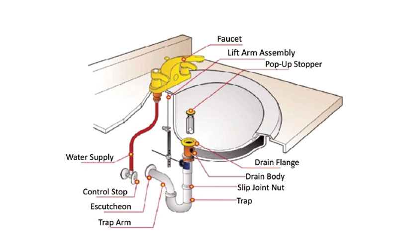
CONTROL STOP AND SLIP JOINT NUT
The conventional method of water distribution is a main and branch system. This system utilizes a main to service several branches, which in turn service individual fixtures.
A parallel water distribution system usually refers to plastic pipe systems, usually PEX or PEX-AL-PEX systems that use a manifold in the system. There are two types of manifold systems:
- The “home run” system utilizes a centrally located manifold to individually distribute supply lines to each fixture (see Figure 606.5b).
- The “remote manifold” system utilizes a trunk or main, which services several small manifolds that in turn service a group of individual fixtures.
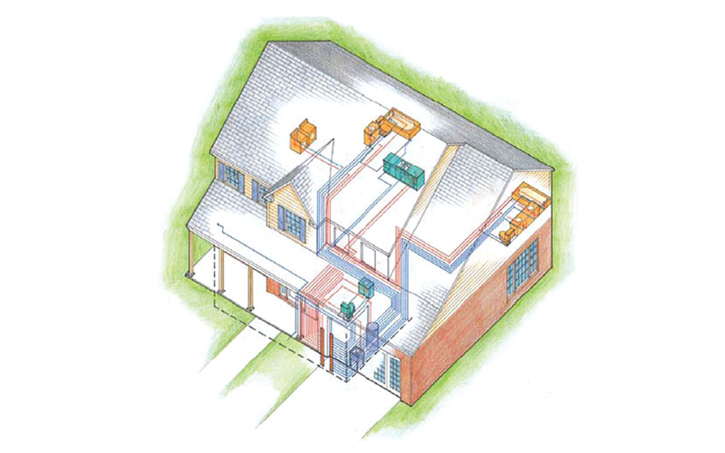
PARALLEL WATER DISTRIBUTION PEX HOME RUN MANIFOLD SYSTEM
The manifold, as long as it incorporates a fullway shutoff valve for each fixture and is not located in an attic, crawl space, or other locations not readily accessible, can be used in lieu of a control valve at the fixture itself. This will entail shutting off the supply to a fixture from the manifold, not an angle stop at the fixture. The ports on the manifold must be properly identified as to the fixture and location it controls. For manifolds located in attics, crawl spaces, or other locations not readily accessible, a shut off valve must be ahead of the fixture or appliance.
All valves and control manifolds within the water supply system shall be accessible no matter where they are located on or about the premises.
From the 2024 UMC Illustrated Training Manual, Chapter 12 – HYDRONICS
1210.3 Hangers and Supports. Pipe and tubing shall be supported in accordance with Section 313.0. Equipment that is part of the piping system shall be provided with additional support in accordance with this code and manufacturer’s installation instructions. Radiant systems utilizing heat emission or transfer plates shall have a gap of at least 1/4 inch (6.4 mm) between adjacent plates.
Besides the forces of thrust and torque in a piping system, there is thermal expansion. The weight of the pipe and its contents are significant. At a little over 8.3 pounds per gallon, water weight adds up fast. Assuming the pipe is full, 4-inch diameter pipe 10 feet long has over 45 pounds of water in addition to the 110 pounds for the 16-gauge galvanized pipe.
Various manufacturers have different products to allow support of piping and equipment (see Figure 1210.3a). Hangers and supports include: beam clamps, pipe hangers, pipe clamps, pipe rollers, pipe supports, concrete inserts, brackets, channels, struts, trays, fasteners, enclosures, etc.
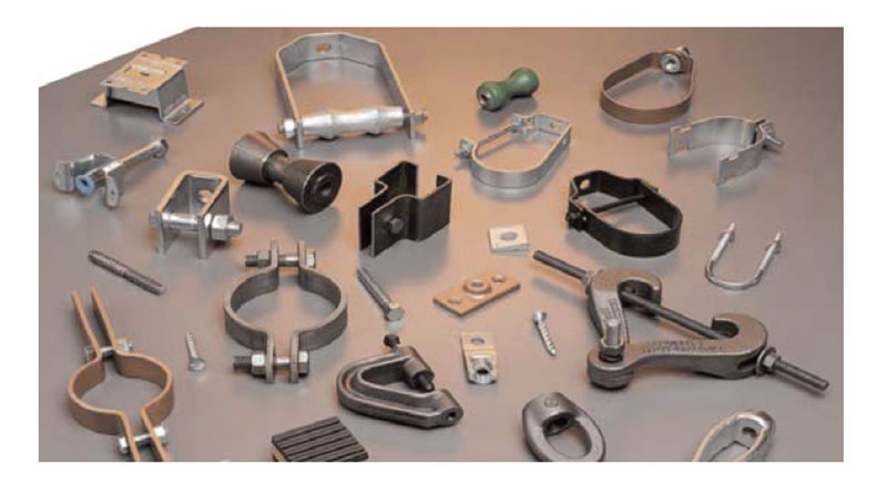
SAMPLES OF PIPE HANGERS (Courtesy of Cooper B-Line)
Hangers and supports are susceptible to dissimilar metal corrosion.
Whichever method is used, “adequately supported” may include:
- Piping should always be kept vertical (plumb) or horizontal (level) to ensure proper alignment of fittings and equipment. Pipe pitched for drainage typically is 1/4-inch pitch per foot of horizontal run.
- Providing support for components connected by piping. (e.g., circulators, low-water cutoffs, expansion tanks).
- Distance between the supports is usually specified by the manufacturer but must always satisfy the AHJ. In certain geographic areas, earthquakes create additional demands on the hanger and support systems. Specialized systems have been developed to survive the unique horizontal loadings (both perpendicular and parallel) that occur during earthquakes (see Figure 1210.3b).
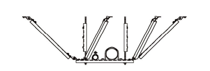
TRAPEZE TRANSVERSE AND LONGITIDINAL BRACING (Courtesy of Cooper B-Line)
The swing joint is a joint of threaded pipes and fittings where the pipe threads allow small amounts of movement during thermal expansion and contraction.
An expansion loop is a loop formed within an otherwise straight run of tubing that can absorb the movement in the pipe due to thermal expansion/contraction.
U-bends, coiled loops, and offset and returns are accepted methods of providing limited expansion of long rigid runs of pipe (see Figure 1210.3c).
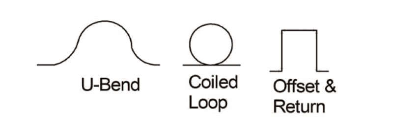
EXAMPLES OF EXPANSION LOOPS (Courtesy of Praxis Green, Inc.)
(This is not to be considered the official position of IAPMO, nor is it an official interpretation of the Codes.)

IAPMO
IAPMO develops and publishes the Uniform Plumbing Code®,the most widely recognized code of practice used by the plumbing industry worldwide; Uniform Mechanical Code®; Uniform Swimming Pool, Spa and Hot Tub Code®; and Uniform Solar Energy, Hydronics and Geothermal Code™ — the only plumbing, mechanical, solar energy and swimming pool codes designated by ANSI as American National Standards — and the Water Efficiency Standard (WE-Stand)™. IAPMO works with government, contractors, labor force, and manufacturers to produce product standards, technical manuals, personnel certification/educational programs and additional resources in order to meet the ever-evolving demands of the industry in protecting public health and safety.
Last modified: October 10, 2024
