August 14, 2025

From the 2024 UPC Illustrated Training Manual, Chapter 9, VENTS
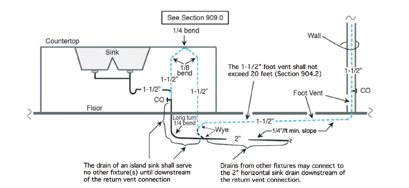
909.1 General. Traps for island sinks and similar equipment shall be roughed in above the floor and shall be permitted to be vented by extending the vent as high as possible, but not less than the drainboard height and then returning it downward and connecting it to the horizontal sink drain immediately downstream from the vertical fixture drain. The return vent shall be connected to the horizontal drain through a wye-branch fitting and shall, in addition, be provided with a foot vent taken off the vertical fixture vent by means of a wye branch immediately below the floor and extending to the nearest partition and then through the roof to the open air, or shall be permitted to be connected to other vents at a point not less than 6 inches (152 mm) above the flood-level rim of the fixtures served. Drainage fittings shall be used on the vent below the floor level, and a slope of not less than 1/4 inch per foot (20.8 mm/m) back to the drain shall be maintained. The return bend used under the drainboard shall be a one-piece fitting or an assembly of a 45 degree (0.79 rad), a 90 degree (1.57 rad), and a 45 degree (0.79 rad) elbow in the order named. Pipe sizing shall be as elsewhere required in this code. The island sink drain, upstream of the returned vent, shall serve no other fixtures. An accessible cleanout shall be installed in the vertical portion of the foot vent.
An island fixture is a fixture remote from a plumbing wall and requires special venting that differs from continuous, individual, common, and wet venting. An island fixture differs from a fixture mounted in cabinets that are attached to a wall forming a peninsula and must be vented according to Section 905.3 as shown in Figure 909.1a. The unique feature of the island vent is that it returns downward to a horizontal vent (foot vent) below the floor before rising vertically above the spill rim of the sink (see Figure 909.1b). Other than floor-mounted fixtures and island fixtures, no other fixture is permitted to have its vent installed below the floor.
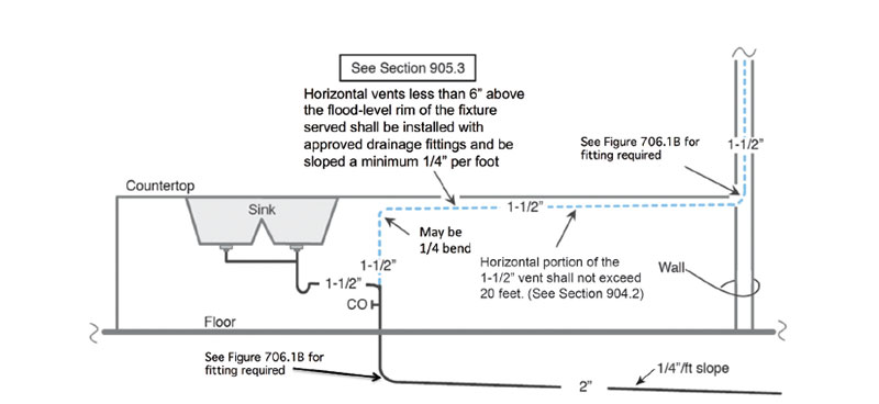
PENINSULA SINK INSTALLATION
The vent from the trap arm connection is required to extend vertically as high as possible inside the cabinet, but not less than the drainboard height. The configuration of the return bend using 45-degree and 90-degree elbows purposes to maintain a vertical angle (see Section 224.0, Vertical Pipe). This is to protect the return bend from accumulating waste and to prevent waste from flowing down the return side of the bend if a blockage occurs.
ISLAND SINK INSTALLATION
Notice in Figure 909.1b how the return vent is connected to both the horizontal vent (foot vent) and the horizontal drain. Wye-branch fittings must be used for both connections and are considered drainage fittings. The wyebranch fitting connecting the return vent to the foot vent is to be in vertical position with the wye-branch sloping down toward the drain rather than up toward the vent, which would better assist air flow. Although frictional resistance of air flow would increase with a down-turned branch fitting, it is insignificant and still allows airflow up the vent to protect the trap seal. The critical reason for the downturned wye fitting at the foot vent connection is the flooding potential of the foot vent in the event of a kitchen waste blockage. Envision a blockage occurring downstream the kitchen drain. The waste would begin to flow up the vertical piping and spill into the foot vent and continue vertically until it spills into the basin of the sink. When the blockage is released, then the waste in the foot vent must flow toward the horizontal drain with a slope of not less than one-fourth of an inch per foot. Therefore, the wyebranch fitting is required to slope down toward the drain and not up toward the vent.
The installation of a cleanout on the vertical component of the foot vent installation is also required. Although not required by code, it is a good idea to install this cleanout above the spill rim of the sink since a drain blockage would allow the vertical section of the foot vent to fill to the same level as the waste spilled into the sink basin. This would allow safe opening of the cleanout for rodding.
FIGURE 909.1A
PENINSULA SINK INSTALLATION
FIGURE 909.1B
ISLAND SINK INSTALLATION
From the 2024 UMC Illustrated Training Manual, Chapter 7, COMBUSTION AIR
701.9 Mechanical Combustion Air Supply. Where all combustion air is provided by a mechanical air supply system, the combustion air shall be supplied from outdoors at the minimum rate of not less than 0.35 cubic feet per minute per 1000 Btu/h [0.034 (m3/min)/kW] for all appliances located within the space. [NFPA 54:9.3.6]
This section allows for the use of mechanical blowers or fans to supply combustion air in lieu of the “gravity” type combustion air openings and ducts outlined in the previous sections. The fan or blower controls must be interlocked with each of the appliances in the room so that appliances will not operate if the fan is not providing the combustion air. The manufacturer’s data sheets for the appliances in the room must be reviewed in the event they have larger rate requirements. If not, the minimum rate required by this section is 0.35 cubic feet per minute (cfm)/1,000 Btu/h of appliance input rating.
Example:
A mechanical room has three furnaces rated at 200,000 Btu/h, each and four “tankless” water heaters rated at 150,000 Btu/h, each. Please calculate the required mechanical ventilation rate needed for combustion air.
Total input rating = (200,000 x 3) + (150,000 x 4)
= 1,200,000 Btu/h
Cubic feet per minute for combustion air
= 1,200,000 x 0.35/1,000
= 420 cfm minimum
(This is not to be considered the official position of IAPMO, nor is it an official interpretation of the Codes.)

IAPMO
IAPMO develops and publishes the Uniform Plumbing Code®,the most widely recognized code of practice used by the plumbing industry worldwide; Uniform Mechanical Code®; Uniform Swimming Pool, Spa and Hot Tub Code®; and Uniform Solar Energy, Hydronics and Geothermal Code™ — the only plumbing, mechanical, solar energy and swimming pool codes designated by ANSI as American National Standards — and the Water Efficiency Standard (WE-Stand)™. IAPMO works with government, contractors, labor force, and manufacturers to produce product standards, technical manuals, personnel certification/educational programs and additional resources in order to meet the ever-evolving demands of the industry in protecting public health and safety.
Last modified: August 13, 2025