April 17, 2025

From the 2024 UMC Illustrated Training Manual, Chapter 10, TRAPS AND INTERCEPTORS
1002.2 Fixture Traps. Each fixture trap shall have a protecting vent so located that the developed length of the trap arm from the trap weir to the inner edge of the vent shall be within the distance given in Table 1002.2 but in no case less than two times the diameter of the trap arm.
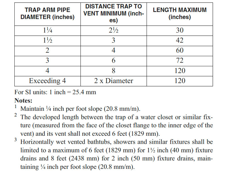
HORIZONTAL LENGTHS OF TRAP ARMS
(EXCEPT FOR WATER CLOSETS AND SIMILAR FIXTURES)1, 2, 3
The effect of length of unvented fixture drains on self-siphonage was the subject of much research at the National Bureau of Standards [see Recommended Minimum Requirements for Plumbing BH13 (1928) and Self-Siphonage of Fixture Traps BMS126 (1951)]. One of the objectives of the research was to find the maximum length of a fixture drain without self-siphoning. This research demonstrated that the slope should be confined between the limits of 1/4 inch and 1/2 inch per foot and that the outlet end of the fixture drain should not extend below the weir of the trap. Hence, Table 1002.2 shows maximum horizontal lengths of trap arms calculated using a grade of 1/4 inch per foot to an extent where the trap arm outlet will not be below the weir of the trap. For example, a 1 1/4 inch trap arm may have a maximum horizontal distance of 30 inches without producing the effect of selfsiphonage (see Figures 1002.2a and 1002.2b).
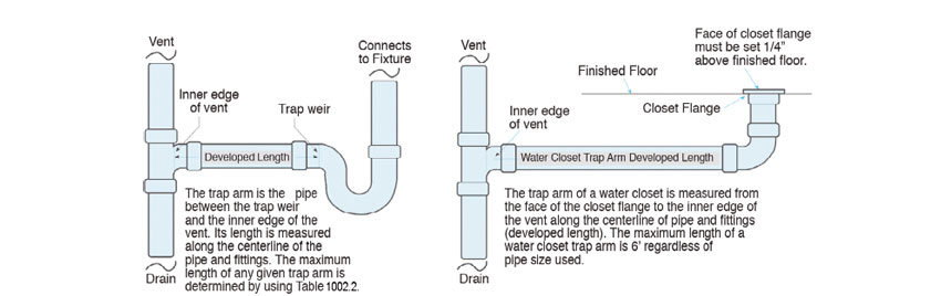
DEVELOPED LENGTH OF TRAP ARM
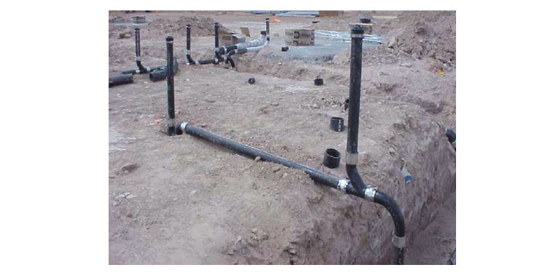
THREE-INCH TRAP ARM
The research also revealed the variations between short and long turn pattern fittings (sanitary tee and combination wye-eighth bend), the short turn fitting permitting the use of longer unvented lengths of fixture drains. Thus, the short turn fitting has better characteristics to prevent selfsiphonage and is preferred when connecting a fixture drain to a vertical vent. The sanitary tee also allows the vent opening to remain above the trap weir. This better allows air into the trap arm while the fixture is draining and retards any momentum pull that could cause siphonage.
Because the water closet and similar integrally trapped fixtures function as self-siphonage fixtures, their traps are an S-type. In this case, the trap arm length is calculated along the developed length of the piping from the top of the closet flange to the inner edge of the vent. Footnote 2 in Table 1002.2 stipulates for the water closet trap arm a maximum length of 6 feet. This limitation is required whether the water closet trap arm is 3 inches in diameter or 4 inches.
The same research discussed above also discovered that the vent could be placed too close to the weir of the trap. A style of venting the trap called the “crown vent” had been used but it was found to be subject to clogging. When the fixture discharges, there is an upward vertical momentum of flow on the outlet side of the trap which would enter the vent if installed on the crown of the trap causing the vent to eventually foul and clog. Also, the vent at the crown of the trap or close to the crown is covered by the initial full flow into the trap arm and is useless to prohibit siphonage. Therefore, there is a minimum trap arm length requirement. The minimum length is two times the diameter of the trap arm. For example, the 1 1/4 inch trap arm must have a minimum distance of 2 1/2 inches from the weir of the trap to the inner edge of the vent. Two times the diameter of the pipe effectively moves the inner edge of the vent away from the area of full flow in the trap arm and allows the vent to function properly (see Figure 1002.2c).

MINIMUM TRAP ARM DISTANCE
Table 1002.2 Note 3 is based upon studies of the National Bureau of Standards (now NIST), which originally helped produce many of the tables and recommendations in the UPC regarding sanitary drainage and vent systems. NIST also investigated horizontal wet vent systems to verify performance for the inclusion into plumbing codes. Their report, BMS 119 Wet Venting of Plumbing Fixtures, found that a 1 1/2-inch bathtub drain sloped at 1/4 inch per foot may have a length of 6’-0” between the horizontal wet vent (from the lavatory) and trap weir of the bathtub while maintaining within the required ±1 inch of water column pressure differential at the fixture trap to mitigate self-siphonage conditions. The study also found that increasing the diameter of the fixture drain from the bathtub to 2 inches allowed a distance of 8’-0” while maintaining the trap seal.
From the 2024 UMC Illustrated Training Manual, Chapter 3, GENERAL REGULATIONS
305.1 Installation in Residential Garages. Appliances in residential garages and in adjacent spaces that open to the garage and are not part of the living space of a dwelling unit shall be installed so that all heating elements, switches, burners, and burner-ignition devices are located not less than 18 inches (457 mm) above the floor.
Exception: Listed flammable vapor ignition resistant (FVIR) appliances. {NFPA 54:9.1.10.1}
Garage areas are especially vulnerable to flammable vapors from potential fuel leaks from vehicles and leaks from stored fuels, paints and solvents. The 18-inch height requirement in this section applies to appliances that could provide a source of ignition, such as those having standing pilots, electronic ignitions, relays, switches, starting switches found inside some types of motors and similar devices. Even electric water heaters having heating elements and switches must be elevated 18 inches above the floor. The 18 inches is to be measured from the floor level to the source of ignition (see Figure 305.1). Please note that there are some newer appliances that are listed for installation at garage floor level (Flammable Vapor Ignition Resistant), as they are designed to shield the ignition source within.
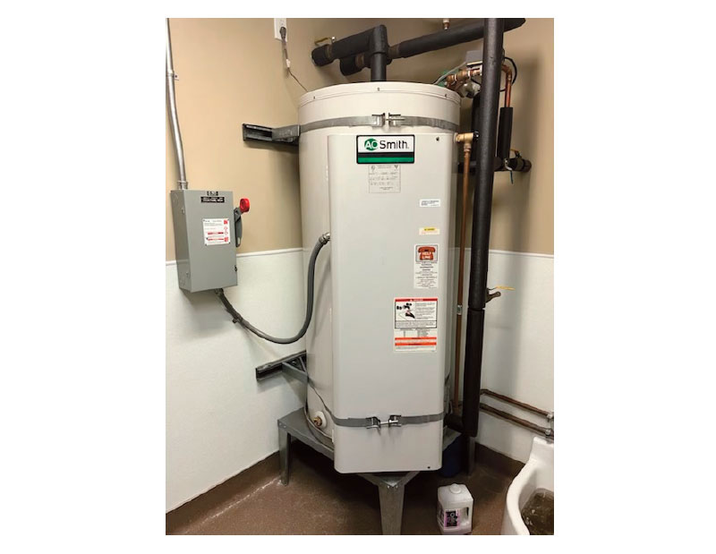
PROTECTION OF APPLIANCES IN GARAGES
(This is not to be considered the official position of IAPMO, nor is it an official interpretation of the Codes.)

IAPMO
IAPMO develops and publishes the Uniform Plumbing Code®,the most widely recognized code of practice used by the plumbing industry worldwide; Uniform Mechanical Code®; Uniform Swimming Pool, Spa and Hot Tub Code®; and Uniform Solar Energy, Hydronics and Geothermal Code™ — the only plumbing, mechanical, solar energy and swimming pool codes designated by ANSI as American National Standards — and the Water Efficiency Standard (WE-Stand)™. IAPMO works with government, contractors, labor force, and manufacturers to produce product standards, technical manuals, personnel certification/educational programs and additional resources in order to meet the ever-evolving demands of the industry in protecting public health and safety.
Last modified: April 17, 2025