October 23, 2025
From the 2024 UPC Illustrated Training Manual, Chapter 6, WATER SUPPLY AND DISTRIBUTION
603.3.3 Hose Connection Backflow Preventer. A hose connection backflow preventer consists of two independent check valves with an independent atmospheric vent between and a means of field testing and draining.
A hose connection vacuum breaker (HVB) should be installed on each faucet or hose bibb connected to the potable water supply to prevent backflow into the water supply. HVB’s must be installed at least six inches above the ground surface. The HVB is an AVB and must follow the installation parameters of Table 603.2. HVBs have a set screw or other method that prevents them from being easily removed once they are installed. This prevents them from being removed when the garden hose is removed. Once the HVB is installed, no further adjustments are required (see Figure 603.3.3).
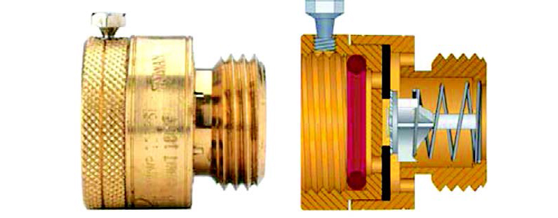
FIGURE 603.3.3
HOSE CONNECTION VACUUM BREAKER
A HVB prevents backflow to the water supply by venting water to the atmosphere (onto the ground) when backflow conditions exist. A spring-loaded check valve is opened by the water supply pressure when outflow occurs through the valve. When pressure is sufficient to open the check valve, flow is directed into the garden hose. When the supply pressure is interrupted or when the pressure in the hose becomes greater than the supply pressure, outflow stops and the spring-loaded check valve closes, simultaneously opening a vent to the atmosphere. In this mode of operation, any water that flows backwards through the HVB is vented onto the ground.
The spring-loaded check valve does not allow drainage of water from between the hose bibb and the upper part of the HVB; thus, freeze protection must be provided, just as all outdoor plumbing would need to be protected under freezing conditions.
HVBs should be inspected and tested periodically to ensure that they are working properly. Fortunately, their mode of operation permits inspections to be easily made. Verify that the check valve closes and the atmospheric vent opens reliably whenever the water supply is shut off. It is very simple to do this if a nozzle that can be shut off is used on the end of the hose. When the nozzle shuts off, turn on the faucet and allow the hose to pressurize. Then, shut off the faucet while the hose is pressurized. After a few seconds, the hose pressure should be released in a small spray as the atmospheric vent suddenly opens.
From the 2024 UMC Illustrated Training Manual, Chapter 9, INSTALLATION OF SPECIFIC APPLIANCES
908.3.3 Multiple-Family or Public Use. All clothes dryers installed for multiple-family or public use shall be installed as specified for a Type 2 clothes dryer under Section 504.4.3.1. [NFPA 54:10.4.7]
A Type 1 clothes dryer is primarily manufactured for use in a single-family environment and may be coin-operated. A Type 2 clothes dryer is designed and listed for use in a business setting utilized by the public (see Section 205.0). General installation and venting requirements are specified in the code and the manufacturer’s installation instructions for Type 1 and 2 dryers.
All dryers shall be exhausted to the outside atmosphere. Rigid duct is to be properly supported to prevent sagging or “traps” and the duct joints sealed in an approved manner. All dryer ducts shall be constructed of metal with a smooth interior surface (see Section 504.0 Environmental Air Ducts). No dryer duct shall be assembled with screws or other fastening methods that penetrate the duct, which can cause lint to accumulate. Lint collection in the duct causes improper dryer operation and a fire hazard. See Section 504.4.2.1 for length limitations.
(This is not to be considered the official position of IAPMO, nor is it an official interpretation of the Codes.)
IAPMO
IAPMO develops and publishes the Uniform Plumbing Code®,the most widely recognized code of practice used by the plumbing industry worldwide; Uniform Mechanical Code®; Uniform Swimming Pool, Spa and Hot Tub Code®; and Uniform Solar Energy, Hydronics and Geothermal Code™ — the only plumbing, mechanical, solar energy and swimming pool codes designated by ANSI as American National Standards — and the Water Efficiency Standard (WE-Stand)™. IAPMO works with government, contractors, labor force, and manufacturers to produce product standards, technical manuals, personnel certification/educational programs and additional resources in order to meet the ever-evolving demands of the industry in protecting public health and safety.
Last modified: October 28, 2025