December 12, 2024
From the 2024 UPC Illustrated Training Manual, Chapter 12 – FUEL GAS PIPING
1208.5.10.3 Compression-Type Mechanical Joints. Where compression-type mechanical joints are used, the gasket material in the fitting shall be compatible with the plastic piping and with the gas distributed by the system. An internal tubular rigid stiffener shall be used in conjunction with the fitting. The stiffener shall be flush with the end of the pipe or tubing and shall extend at least to the outside end of the compression fitting when installed. The stiffener shall be free of rough or sharp edges and shall not be a force fit in the plastic. Split tubular stiffeners shall not be used. [NFPA 54:5.5.8(3)]
Compression-type mechanical joints for plastic piping come in many forms and materials. The components are generally a body; a threaded compression nut; an elastomer seal ring or O-ring; a stiffener and, in some cases, a grip ring (see Figure 1208.5.10.3a). The seal and grip rings, when compressed, grip the outside of the pipe, affecting a pressure-tight seal and, in most designs, providing pullout resistance that exceeds the yield strength of the polyethylene pipe. It is important that the inside of the pipe wall be supported by the stiffener under the seal ring and under the gripping ring (if incorporated in the design) to avoid deflection of the pipe. A lack of this support could result in a loss of the seal or the gripping of the pipe for pullout resistance. This fitting style is normally used in service lines for gas or water pipe two inches (50 mm) Iron Pipe Size (IPS) and smaller. It is also important to consider that three categories of this type of joining device are available. The compression type is recommended to provide a seal only, the stab type provides a seal and some restraint from pullout and the mechanical bolt type provides a seal plus full pipe restraint against pullout.
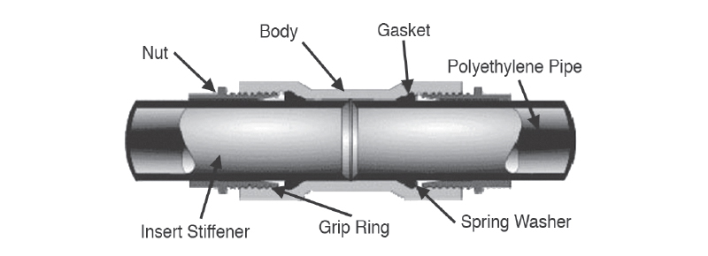
POLYETHYLENE PIPE COMPRESSION JOINT
Stab-type mechanical fittings also have many styles; however, the design concept, as illustrated in Figure 1208.5.10.3b, is similar in most styles. Internally, there are specially designed components, including an elastomer seal, such as an O-ring, and a gripping device to affect pressure sealing and pullout resistance capabilities. Self-contained stiffeners are included in this design. With this style fitting, the operator prepares the pipe ends, marks the stab depth on the pipe and “stabs” the pipe into the depth prescribed for the fitting being used. These fittings are available in sizes from one-half-inch Copper Tubing Size (CTS) through two inches IPS and are all of ASTM D 2513(2) Category I design, indicating seal and full restraint against pullout.
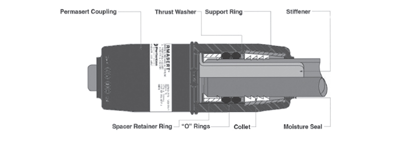
POLYETHYLENE PIPE STAB-TYPE JOINT
Mechanical bolt-type couplings for large diameter pipes are available to join polyethylene to polyethylene or other types of pipe such as PVC, steel and cast iron in sizes from 1 1/4 inches IPS and larger. Components for this style of fitting are shown in Figure 1208.5.10.3c. As with the mechanical compression fittings, these couplings work on the general principle of compressing an elastomeric gasket around each pipe end to be joined in order to form a seal. The gasket, when compressed against the outside of the pipe by tightening the bolts, produces a pressure seal.
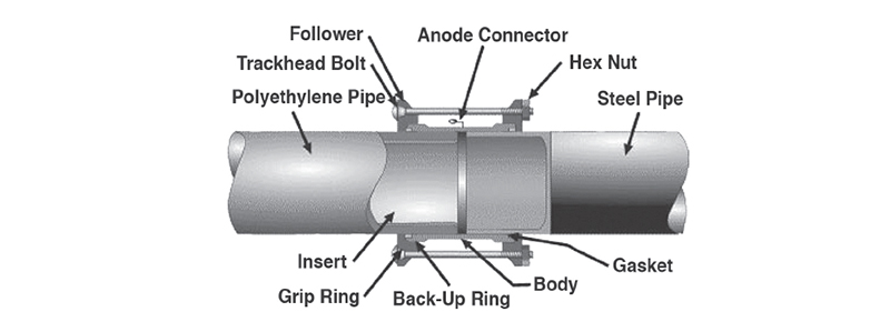
POLYETHYLENE PIPE MECHANICAL BOLT-TYPE JOINT
From the 2024 UMC Illustrated Training Manual, Chapter 10 – BOILERS AND PRESSURE VESSELS
1003.4 Stack Dampers. Stack dampers on boilers fired with oil or solid fuel shall not close off more than 80 percent of the stack area. Operative dampers shall not be placed within a stack, flue, or vent of a gas-fired boiler.
Exception: Automatic boilers with prepurge, automatic draft control, and interlock.
Stack dampers and vent dampers perform the same basic function – they stop chimney draft from drawing heated air from the building. Generally, stack dampers are bimetal and thermally activated while vent dampers tend to be electrical and automatically controlled (see Figure 1003.4).
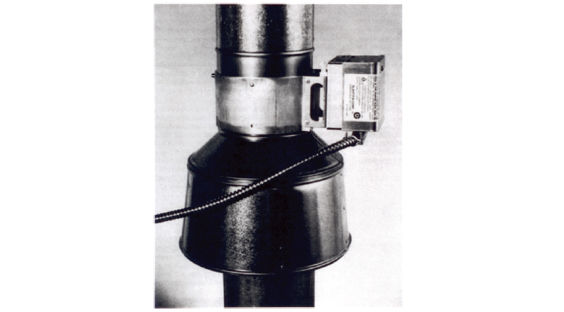
AUTOMATIC VENT DAMPER
(Courtesy of Slant Fin)
When the vent or stack is left open when the boiler is not firing, conditioned air is pulled through the chimney due to “stack effect.” Also, a closed damper substantially reduces boiler standby losses.
Electrically controlled vent dampers rotate to their open position when the boiler is going to fire. An interlock prevents burner operation unless the damper is verified open by an integral switch. If the damper does not open, the burner circuit will not be completed and the burner will not be allowed to fire. When the burner shuts down, the damper will rotate to the closed position.
Under no circumstances should a damper interlock be bypassed.
(This is not to be considered the official position of IAPMO, nor is it an official interpretation of the Codes.)

IAPMO
IAPMO develops and publishes the Uniform Plumbing Code®,the most widely recognized code of practice used by the plumbing industry worldwide; Uniform Mechanical Code®; Uniform Swimming Pool, Spa and Hot Tub Code®; and Uniform Solar Energy, Hydronics and Geothermal Code™ — the only plumbing, mechanical, solar energy and swimming pool codes designated by ANSI as American National Standards — and the Water Efficiency Standard (WE-Stand)™. IAPMO works with government, contractors, labor force, and manufacturers to produce product standards, technical manuals, personnel certification/educational programs and additional resources in order to meet the ever-evolving demands of the industry in protecting public health and safety.
Last modified: December 12, 2024
