February 29, 2024
From the 2024 UPC Illustrated Training Manual, Chapter 5, WATER HEATERS
509.6.2.2 Vent Offsets. Type B and Type L vents sized in accordance with Section 509.6.2.1(3) or Section 509.6.2.1(4) shall extend in a generally vertical direction with offsets not exceeding 45 degrees (0.79 rad), except that a vent system having not more than one 60 degree (1.05 rad) offset shall be permitted. Any angle greater than 45 degrees (0.79 rad) from the vertical is considered horizontal. The total horizontal distance of a vent plus the horizontal vent connector serving draft hood-equipped appliances shall not be greater than 75 percent of the vertical height of the vent. [NFPA 54:12.7.4.2]
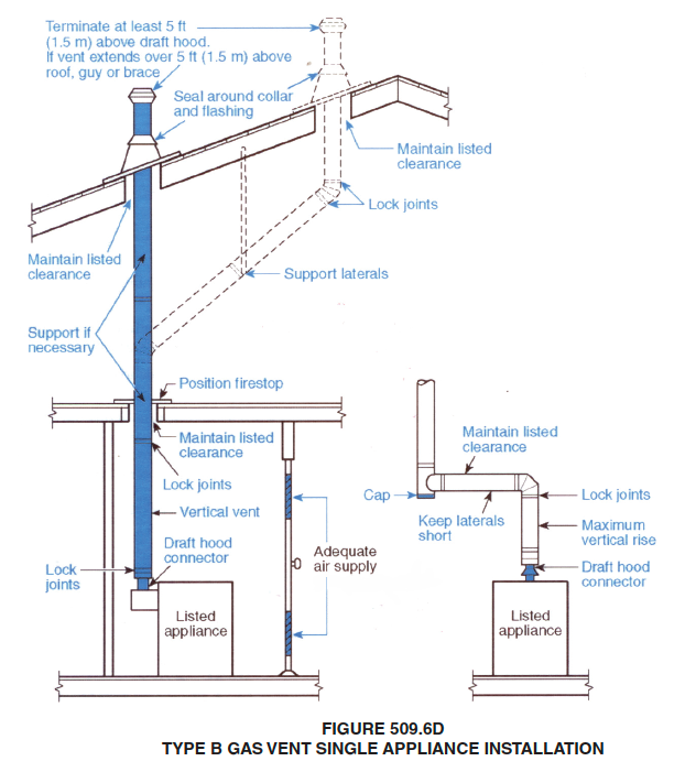
A Type B or L gas vent is limited to one 60-degree offset as shown in Figure 509.6d. The offset is also limited to 75 percent of the total vertical height of the vent. If the system is designed and sized in accordance with the tables in Section 510.0, a Type B gas vent can include two 90-degree turns and a horizontal run greater than 75 percent of the vertical portion of the vent. For systems with more than two 90-degree turns, Sections 510.2.4 and 510.2.5 permit the use of level or if the outlet is blocked. When such stoppage occurs, all vent gases from appliances operating below the obstruction will exit through the upper draft hood relief opening rather than through the vent outlet. Large quantities of vent gases will be dumped into the space containing those appliances immediately below the obstruction, while at the same time the appliances located at lower levels will appear to be operating normally.
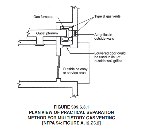
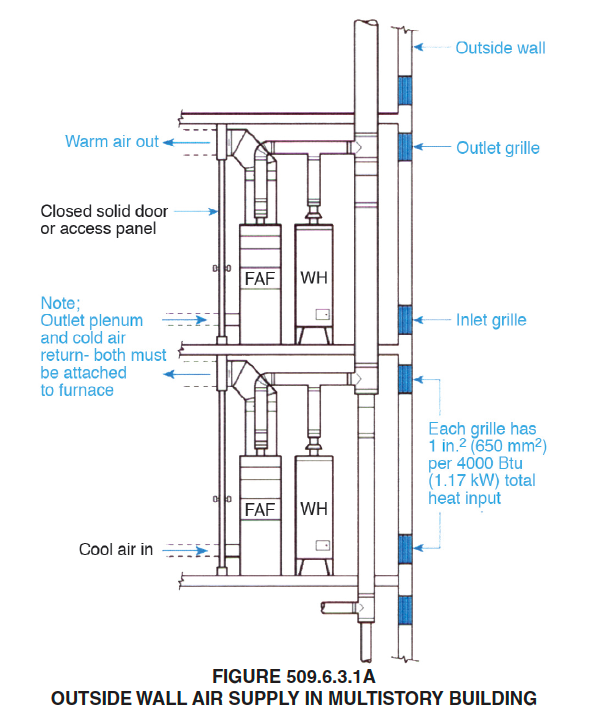
One practical plan to separate or isolate appliances, if installation can be made adjacent to an outside wall, is shown by Figure 509.6.3.1 and Figure 509.6.3.1a. Access to the appliance room is through a door that opens onto an outdoor balcony. A panel separates the appliance room from the inside of the building. If the appliance is a central furnace, the cold air return and outlet ducts are attached to the furnace.
No requirements are given in the code for installation of Category II, III or IV appliances using a common vent in multistory buildings. A Category II, III or IV appliance must be installed in accordance with the terms of its listing and the manufacturer’s instructions. Category I appliance common vents are not usually suitable for venting Category II, III or IV appliances.
From the 2024 UMC Illustrated Training Manual, Chapter 10, BOILERS AND PRESSURE VESSELS
1005.2 Discharge Piping. The discharge piping serving a temperature relief valve, pressure relief valve, or combination of both shall have no valves, obstructions, or means of isolation and provided with the following:
(1) Not less than the size of the valve outlet and shall discharge full size to the flood level of the area receiving the discharge and pointing down.
(2) Materials shall be rated at not less than the operating temperature of the system and approved for such use or shall comply with ASME A112.4.1.
(3) Discharge pipe shall discharge independently by gravity through an air gap into the drainage system or outside of the building with the end of the pipe not exceeding 2 feet (610 mm) and not less than 6 inches (152 mm) above the ground and pointing downwards.
(4) Discharge in such a manner that does not cause personal injury or structural damage.
(5) No part of such discharge pipe shall be trapped or subject to freezing.
(6) The terminal end of the pipe shall not be threaded.
(7) Discharge from a relief valve into a water heater pan shall be prohibited.
(8) Discharge to a termination point that is readily visible.
The waste pipe from the valve should end between two feet and six inches above the floor or drain and should be unthreaded to prevent tampering. Common field practice is to end the waste pipe not more than 6 inches above the floor to reduce splashing and scalding potential during discharge. The end of the discharge tube should be readily visible so that if the relief valve is leaking or open, it can be easily seen.
The primary purpose of a pressure-relief valve is protection of life and property by venting fluid from an over pressurized vessel. Even though it may seem obvious, a manufacturer was compelled to state in its specification sheet, “This device is designed for emergency safety release and shall not be used as an operating control.”
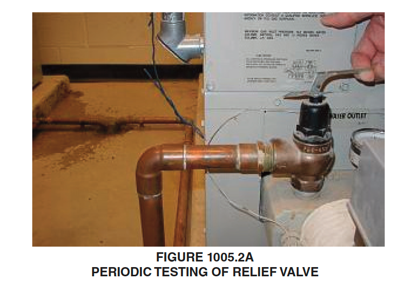
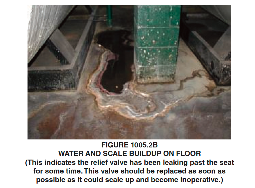
Periodically check that the valve can open and is not corroded closed, which could make it ineffective (see Figures 1005.2a and 1005.2b).
(This is not to be considered the official position of IAPMO, nor is it an official interpretation of the Codes.)

IAPMO
IAPMO develops and publishes the Uniform Plumbing Code®,the most widely recognized code of practice used by the plumbing industry worldwide; Uniform Mechanical Code®; Uniform Swimming Pool, Spa and Hot Tub Code®; and Uniform Solar Energy, Hydronics and Geothermal Code™ — the only plumbing, mechanical, solar energy and swimming pool codes designated by ANSI as American National Standards — and the Water Efficiency Standard (WE-Stand)™. IAPMO works with government, contractors, labor force, and manufacturers to produce product standards, technical manuals, personnel certification/educational programs and additional resources in order to meet the ever-evolving demands of the industry in protecting public health and safety.
Last modified: February 29, 2024
