Presented by SMART Local 104 (Livermore, California) Codes and Standards Representative Randy Young, the Uniform Mechanical Code (UMC®) seminar at IAPMO’s 94th annual Education and Business Conference highlighted new and amended provisions in the 2024 UMC that differ from previous editions.
Since 1985, Young has worked in every aspect of the trade from manufacturing, installation, maintenance, and service of commercial HVAC systems. He also participated in various codes and standards development processes for IAPMO and ASHRAE, serving on the UMC Technical Committee for several code development cycles and chairing numerous task groups.
“I’m really going to focus on a few of the 186 code changes that were proposed in 2024
because if I covered them all we’d be here all week,” Young said. “So, I’m going to talk about chapters 3, 4, 6, a little bit about chapter 11, which is probably the most debated language in here, and chapter 17.”
311.0 Heating or Cooling Air System.
311.1 Source. A heating or cooling air system shall be provided with return air, outside air, or both.
A heating or cooling air system regulated by this code and designed to replace required ventilation shall be arranged to discharge into a conditioned space not less than the amount of outside air specified in Chapter 4.
311.2 Air Filters. Air filters shall be installed in a heating, cooling, or makeup air system. Media-type air filters shall comply with UL 900. Electrostatic and high efficiency particulate filters shall comply with Section 935.0.
Exceptions:
(1) Air filters used in systems serving single guest rooms or dwelling units shall not be required to be listed.
(2) Air filters used in listed appliances and in accordance with the manufacturer’s instructions.
“So, air filters serving a single guest room or dwelling unit do not need to be a listed filter,” he said. “Something that serves a single ADU, accessory dwelling area that only serves one room, those filters don’t have to be listed.”
311.2.1 Minimum Filtration. In mechanically ventilated buildings, occupied areas of the building shall be provided with air filtration media for outside and return air that provides not less than a Minimum Efficiency Reporting Value (MERV) of 13 or as required by the Authority Having Jurisdiction. Installed filters shall be clearly labeled by the manufacturer indicating the MERV rating.
“When we made that change, we had to make the adjustment for the unitary systems so we didn’t lump those in with MERV 13 rating because those smaller units are never going to be able to handle that MERV 13 rating,” Young said. “So, as an inspector it probably won’t cause much new work for you guys, but it’s something to pay attention to.”
Young then moved onto Chapter 4, Ventilation Air.
“We’re going to talk about bird screens, location, rain containment, rain intrusion, and snow entrainment,” he said. “Those are all outdoor air intakes.”
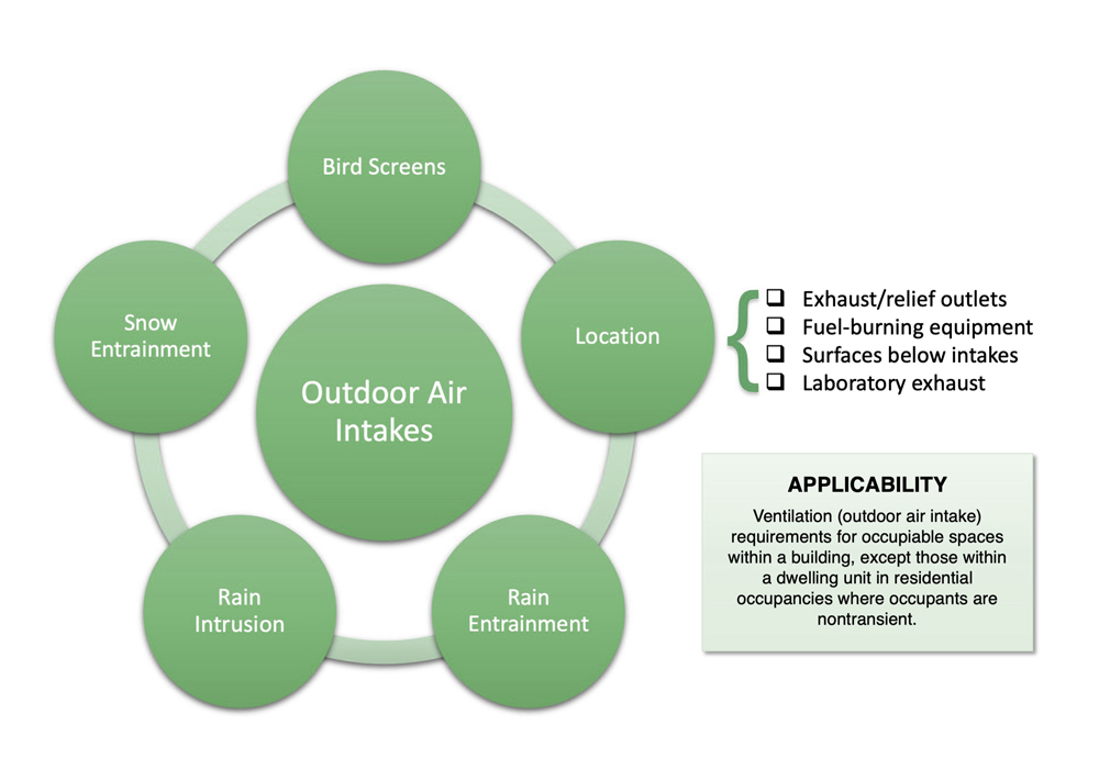
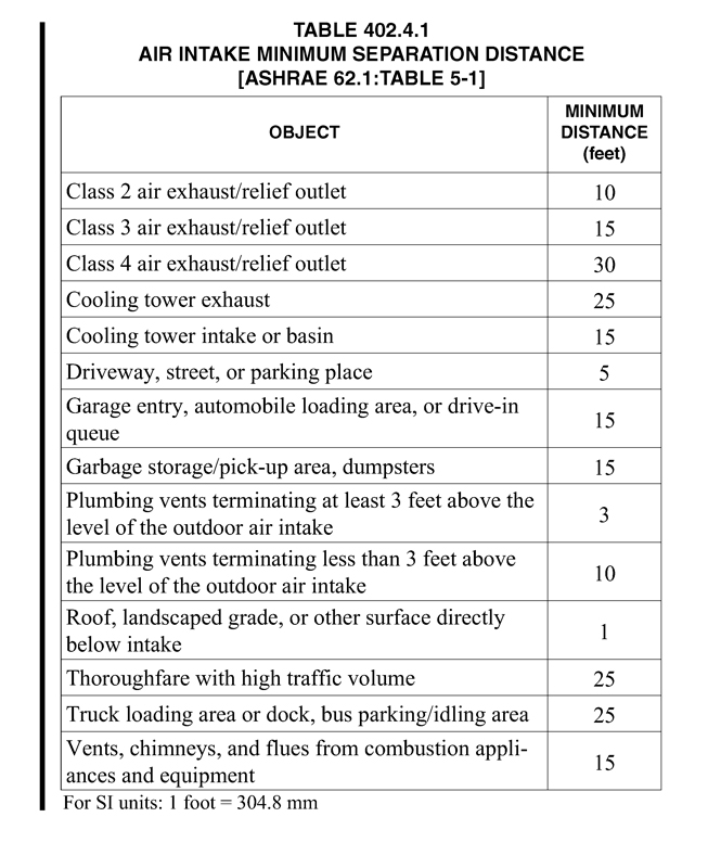
Chapter 4 Ventilation Air – Section 402.4.1 (Location).
402.4 Outdoor Air Intakes. Ventilation system outdoor air intakes shall be designed in accordance with Section 402.4.1 through Section 402.4.5. [ASHRAE 62.1:5.5]
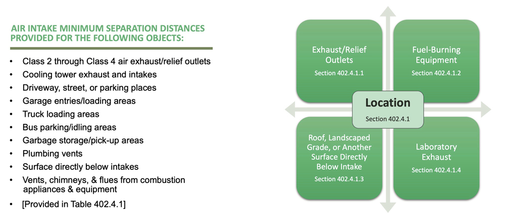
402.4.1 Location. Outdoor air intakes (including openings that are required as part of a natural ventilation system) shall be located such that the shortest distance from the intake to any specific potential outdoor contaminant source listed in Table 402.4.1 shall be equal to or greater than the following:
(1) The separation distance in Table 402.4.1 or
(2) The calculation methods in ASHRAE 62.1 Normative Appendix B and shall comply with all other requirements of this section. [ASHRAE 62.1:5.5.1]
“Section 402.4.1 is going to tell you the distances required for each different application,” he said.
402.4.1.2 Fuel-Burning Equipment. The minimum distances relative to fuel-fired appliances shall be as required by NFPA 54/ANSI Z223.1 for fuel-gas-burning appliances and equipment, NFPA 31 for oil burning appliances and equipment, and NFPA 211 for other combustion appliances and equipment. [ASHRAE 62.1:5.5.1.2]
“We reference those standards, but it’s not necessary for you guys to have the entire standards on hand, but we give you enough information in the code that you should know by the NFPA references if you need more information where you can look it up and get more detail,” Young said.
402.4.1.3 Roof, Landscaped Grade, or Another Surface Directly Below Intake. Where snow accumulation is expected, the surface of the snow at the expected average snow depth shall be considered to be a surface directly below an intake.
Exception: The minimum separation distance in Table 402.4.1 shall not apply where outdoor surfaces below the air intake are sloped more than 45 degrees (0.79 rad) from horizontal or where such surfaces are less than 1 inch (25.4 mm) in width. [ASHRAE 62.1:5.5.1.3]
“This is kind of unusual and unique in my mind because now we have to take into consideration the annual snowfall amount in a certain area,” he said. “That could be subjective.”
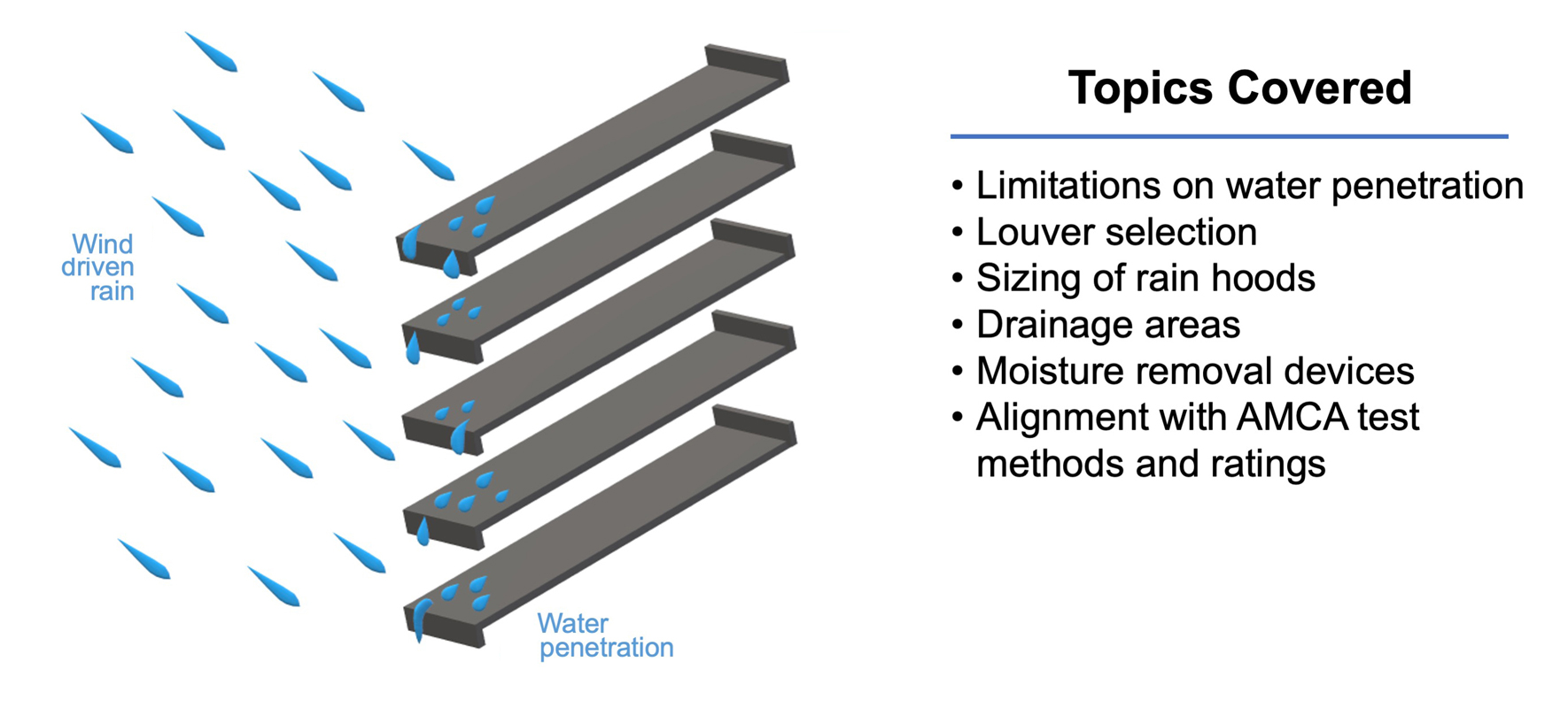
402.4.2 Rain Entrainment. Outdoor air intakes that are part of the mechanical ventilation system shall be designed to manage rain entrainment in accordance with one or more of the following:
(1) Limit water penetration through the intake to 0.07 oz/(ft2•h) [21.5 g/(m2•h)] of inlet area when tested using the rain test apparatus described in UL 1995.
(2) Select louvers that limit water penetration to a maximum of 0.01 oz/ft2 (3.05 g/m2) of louver free area at the maximum free area intake velocity through the louver. This water penetration rate shall be determined when subjected to the water penetration test in AMCA 500-L or equivalent. Manage the water that penetrates the louver by providing a drainage area or moisture removal devices.
(3) Select louvers that are Class A when rated according to AMCA 511 and tested per the AMCA 500-L wind-driven rain test when subjected to a simulated rainfall of 3 inches (76 mm) per hour and a 29 mph (13 m/s) wind velocity. The maximum design core area velocity through the louver shall correlate to a Class A rating.
(4) Use rain hoods sized for no more than 500 feet per minute (2.5 m/s) face velocity with a down- ward-facing intake such that all intake air passes upward through a horizontal plane that intersects the solid surfaces of the hood before entering the system.
(5) Manage the water that penetrates the intake opening by providing a drainage area or moisture removal devices. {ASHRAE 62.1:5.5.2}
“Chapter 4 also covers rain entrainment,” he said. “Does everybody know what rain entrainment is? Rain intrusion is the act of wrongful entering. Rain entrainment is movement of water through the system. Once it gets into the system where does it go after it gets into the ductwork.”
402.4.3 Rain Intrusion. Air-handling and distribution equipment mounted outdoors shall be designed to prevent rain intrusion into the airstream when tested at design airflow and with no airflow, using the rain test apparatus described in UL 1995. [ASHRAE 62.1:5.5.3]
“You might have some issues with this in the field because there are times when the outside air vent is not factory made but instead is made by a shop that is doing the HVAC or ventilation systems,” Young said. “They’re not going to test for AMCA; they’re going to build for AMCA.”
402.4.4 Snow Entrainment. Where climate dictates, outdoor air intakes that are part of the mechanical ventilation system shall be designed as follows to manage water from snow that is blown or drawn into the system:
(1) Access doors to permit cleaning of wetted surfaces shall be provided.
(2) Outdoor air ductwork or plenums shall pitch to drains designed in accordance with the requirements of ASHRAE 62.1. [ASHRAE 62.1:5.5.4]
“This is applicable to climates that are expected to experience snowfall, addresses outdoor intakes that are part of the mechanical ventilation system, and lists design requirements to manage water from snow that is blown or drawn into the system,” he said.
402.4.5 Bird Screens. Outdoor air intakes shall include a screening device designed to prevent penetration by a 0.5 inch (13 mm) diameter probe. The screening device material shall be corrosion resistant. The screening device shall be located, or other measures shall be taken, to prevent bird nesting within the outdoor air intake. [ASHRAE 62.1:5.5.5]
Young then moved into a new requirement regarding air balance.
403.10 Air Balance. All mechanical ventilation systems shall be tested, balanced, and operated to demonstrate that the installation and performance of the systems are in accordance with the design intent. All testing and balancing shall be performed by a technician certified by the Associated Air Balance Council (AABC), the National Environmental Balancing Bureau (NEBB), the Testing, Adjusting and Balancing Bureau (TABB), or other equivalent approved agencies.
Exception: For single family residential, compliance with Section 403.10 shall not be required.
“All, not some, but all,” he said. “Air balancing is proportionately going through the system adjusting the components in order to get the proper amount of air out of each outlet. There are requirements in some states that mandate an air balance report. We hope this provision will help bring that to light for everybody.”
405.4 Kitchen Exhaust. A mechanical exhaust system that discharges directly to the outdoors shall be provided in each kitchen. The fan shall run intermittently (on demand) or continuously. A readily accessible manual control designed to be operated as needed or an automatic control shall be provided for intermittent operations.
Exception: Recirculating systems installed in accordance with Section 516.0 and the manufacturer’s installation instructions.
“Each one has to discharge outdoors now; clearly written,” he said.
405.4.1 Exhaust Rate. For intermittent-controlled operations, the exhaust rate shall be not less than 100 ft3/min (47.2 L/s) for range hoods or 300 ft3/min (142 L/s) for mechanical exhaust fans including downdraft appliances. For continuous operated ventilation, the exhaust rate shall be not less than 50 ft3/min (23.6 L/s).
“What they did here is took out the air changes and put in the minimum 50 foot,” he said.
502.2 Termination of Exhaust Ducts. Exhaust ducts shall terminate in accordance with Section 502.2.1 through Section 502.2.4. Classes of air shall be as defined in Section 203.0 and classified in Section 403.9.
502.2.1 Environmental, Class 1, and Class 2 Air Ducts. Environmental, Class 1, and Class 2 air duct exhaust shall terminate not less than 3 feet (914 mm) from a property line, 10 feet (3048 mm) above a public way, 3 feet (914 mm) from openings into the building and the minimum separation distance from ventilation system outdoor air intakes determined in accordance with Section 402.4.1. The discharge of dryer exhaust ducts shall not terminate over a public way or over an area where condensate or vapor could create a nuisance or hazard.
“This has been a topic of discussion at least the last four code cycles and I think it’s primarily driven by the engineers who are having tighter and tighter spaces and more components inside a building, giving them a little more freedom of where they can dump the air,” he said.
505.8 Product-Conveying Duct Classifications.
Product-conveying ducts shall be classified according to their use, as follows:
Class 1 – Ducts conveying nonabrasives, such as smoke, spray, mists, fogs, noncorrosive fumes and gases, light fine dusts, or powders.
Class 2 – Ducts conveying moderately abrasive particulate in light concentrations, such as saw-dust and grain dust, and buffing and polishing dust.
Class 3 – Ducts conveying Class 2 materials in high concentrations and highly abrasive materials in low concentrations, such as manganese, steel chips, and coke.
Class 4 – Ducts conveying Class 3 materials in high concentrations and highly abrasive material in high concentrations, such as alumina, bauxite, iron silicate, sand, and slag.
Class 5 – Ducts conveying corrosives, such as acid vapors.
“So, they just made it more clear what materials may be in there,” he said.
602.2 Combustibles Within Ducts or Plenums. Materials exposed within ducts or plenums shall be noncombustible or shall have a flame spread index not to exceed 25 and a smoke-developed index not to exceed 50, where tested as a composite product in accordance with ASTM E84 or UL 723. Plastic piping installed in plenums shall be tested in accordance with all requirements of ASTM E84 or UL 723. Mounting methods, supports and sample sizes of materials for testing that are not specified in ASTM E84 or UL 723 shall be prohibited.
Exceptions:
(1) Return-air and outside-air ducts, plenums, or concealed spaces that serve a dwelling unit.
(2) Air filters in accordance with the requirements of Section 311.2.
(3) Water evaporation media in an evaporative cooler.
(4) Charcoal filters where protected with an approved fire suppression system.
(5) Products listed and labeled for installation within plenums in accordance with Section 602.2.1 through Section 602.2.4.
(6) Smoke detectors in accordance with the requirements of Section 609.0.
(7) Duct insulation, coverings, and linings and other supplementary materials installed in accordance with Section 605.0.
(8) Materials in a hazardous fabrication area including the areas above and below the fabrication area sharing a common air recirculation path with the fabrication area.
(9) Plastic water distribution piping listed and labeled for use in plenums in accordance with UL 2846 as having a peak optical density not greater than 0.50, an average optical density not greater than 0.15, and a flame spread distance not greater than 5 feet (1524 mm), and installed in accordance with its listing, shall be permitted.
“I personally don’t like to put anything in a duct or plenum, but sometimes you have to,” Young said. “So, this is telling you now you can utilize the ASTM E84 test method to make sure the pipe is good enough to go into the duct or the plenum.”
602.5.4 Fibrous Glass Duct. Fibrous glass ducts, plenums, or fittings shall be constructed in accordance with SMACNA Fibrous Glass Duct Construction Standards or NAIMA Fibrous Glass Duct Construction Standards.
“As sheet metal workers, it’s important to know which standards you’re building duct work to,” he said. “That’s why we have SMACNA Metal Construction Standards and now we have SMACNA Fibrous Glass Duct Constructions Standards and NAIMA. NAIMA’s been around a long time as well and we didn’t want to exclude them, so now you have two standards you can follow to build a fibrous duct.”
603.1.1 Pressure Classification. The pressure classification of ducts shall be not less than the design operating pressure of the air distribution in which the duct is utilized. All ducts regardless of pressure classification(s) shall be sealed to Seal Class A.
“All openings, all seams, all locks, all components, all penetrations — everything is sealed,” Young said. “That should help stop some of the energy loss we experience and make systems more efficient.”
603.9 Joints and Seams of Ducts. Joints and seams for duct systems shall comply with SMACNA HVAC Duct Construction Standards – Metal and Flexible, SMACNA Round Industrial Duct Construction Standards, or SMACNA Rectangular Industrial Duct Construction Standards, as applicable.
Joints of duct systems shall be made substantially airtight by means of tapes, mastics, gasketing, or other means. All ducts shall be sealed to Seal Class A. Crimp joints for round ducts shall have a contact lap of not less than 1 1⁄2 inches (38 mm) and shall be mechanically fastened by means of not less than three sheet-metal screws equally spaced around the joint, or an equivalent fastening method.
“And, yes, the industrial standards are different from your regular standards,” he said. “You’re using different types of materials, different thicknesses, most of it’s welded so there are not the seams you would normally have.”
605.1.2 Duct Coverings and Linings. Insulation applied to the interior or exterior surface of ducts located in buildings, including duct coverings, linings, tapes, and adhesives, shall have a flame- spread index not to exceed 25 and a smoke- developed index not to exceed 50, where tested in accordance with ASTM E84 or UL 723. The specimen preparation and mounting procedures of ASTM E2231 shall be used. Air duct coverings and linings shall not flame, glow, smolder, or smoke where tested in accordance with ASTM C411 at the temperature to which they are exposed in service. In no case shall the test temperature be less than 250°F (121°C). Coverings shall not penetrate a fire-resistance-rated assembly. The duct coverings and linings shall be listed and labeled.
“Have any of you seen that bubble wrap they use for insulations sometimes?” Young asked. “Is that UL 181 listed? You see it all the time. You know it’s cheap, it’s easy to install and it doesn’t come off, but it’s not UL 181 listed.”
606.6 Periodic Testing and Inspection. Testing and inspection of dampers shall be in accordance with the following:
(1) Smoke dampers shall be tested in accordance with NFPA 105.
(2) Fire dampers shall be tested in accordance with NFPA 80.
(3) Combination fire/smoke dampers shall be tested in accordance with NFPA 80 and NFPA 105.
“We added this language because smoke and fire dampers are supposed to be periodically inspected and they’re not,” he said. “There are dampers that have been installed 10 years ago that haven’t been inspected to see if they operate properly. NFPA 105 and 80 call for periodic damper testing, which is why this was added.”
1103.1 Classification of Refrigerants.
Refrigerants shall be classified in accordance with Table 1102.3 or in accordance with ASHRAE 34 where approved by the Authority Having Jurisdiction.
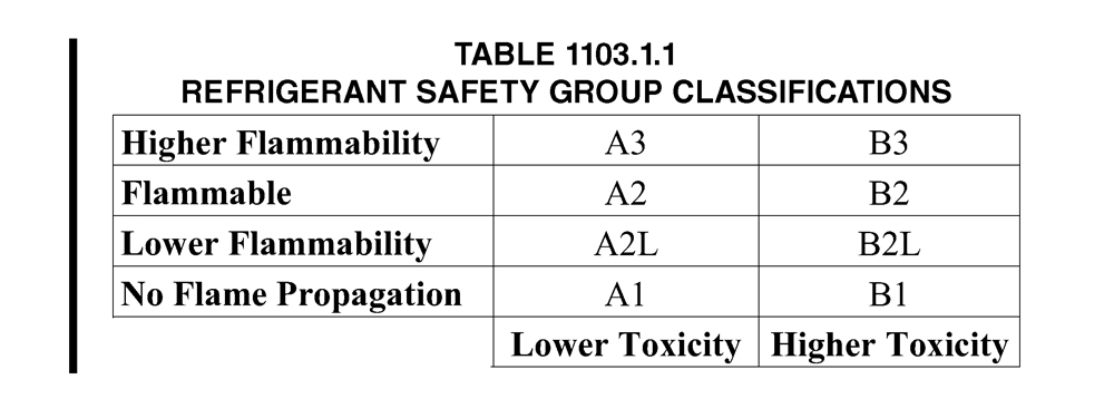
1103.1.1 Safety Group. Table 1102.3 classifies refrigerants by toxicity and flammability, and assigns safety groups using combinations of toxicity class and flammability class. For the purposes of this chapter, the refrigerant Groups A1, A2L, A2, A3, B1, B2L, B2, and B3 shall be considered to be individual and distinct safety groups, as shown in Table 1103.1.1. Each refrigerant is assigned into not more than one group.
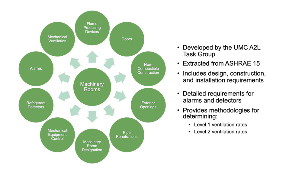
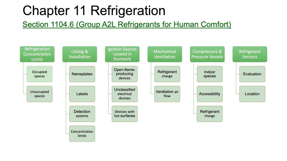
1104.6 Group A2L Refrigerants for Human Comfort. High-probability systems using Group A2L refrigerants for human comfort applications shall comply with this section. [ASHRAE 15:7.6]
1104.6.1 Refrigerant Concentration Limits. Occupied spaces shall comply with the releasable charge limitations of the equipment listing and ASHRAE 15. Unoccupied spaces with refrigerant containing equipment, not including continuous piping or tubing, shall comply with the releasable charge limitations of the equipment listing or Section 1104.6.4. {ASHRAE 15:7.6.1-7.6.1.2}
1104.6.2 Listing and Installation Requirements. Refrigeration systems shall be listed and shall be installed in accordance with listing, the manufacturer’s instructions, and any markings on the equipment restricting the installation. [ASHRAE 15:7.6.2]
1104.6.2.1 Nameplate. The nameplate required by Section 1115.5 shall include a symbol indicating that a flammable refrigerant is used, as specified by the product listing. [ASHRAE 15:7.6.2.1]
1104.6.2.2 Labeling. A label indicating a flammable refrigerant is used shall be placed adjacent to service ports and other locations where service involving components containing refrigerant is performed, as specified by the product listing. [ASHRAE 15:7.6.2.2]
1104.6.2.3 Refrigerant Detection Systems. Refrigerant detection systems shall be in accordance with the listing and ASHRAE 15.
1104.6.2.4 Refrigerant Concentration Above Limit. When the refrigerant detection system senses a refrigerant exceeding its setpoint, the following actions shall be taken:
(1)The supply air fan of the equipment shall activate with a minimum airflow rate specified by the manufacturer.
(2) Turn off the compressor and all other electrical devices, excluding the control
power transformers, control systems, and the supply air fan. The supply air fan shall continue to operate for at least five minutes after the refrigerant detection system has sensed a drop in the refrigerant concentration below the value specified in Section 1104.6.6(b).
Exception: The compressor operation shall not be turned off when the compressor operation reduces the leak rate or the total amount of released refrigerant to the indoor space.
(3)Any device that controls airflow located within the product or in ductwork that supplies air to the occupied space shall be fully open. Any device that controls airflow shall be listed.
(4)Mitigation action required by the equipment listing shall be initiated. {ASHRAE 15:7.6.2.4}
1104.6.3 Ignition Sources Located in Ductwork.
Open-flame-producing devices shall not be permanently installed in the ductwork that serves the space. Unclassified electrical devices shall not be located within the ductwork that serves the space. Devices containing hot surfaces exceeding 1290°F (700°C) shall not be located in the ductwork that serves the space unless there is a minimum airflow of 200 ft/min (1.0 m/s) across the heating device(s) and there is proof of airflow before the heating device(s) is energized. [ASHRAE 15:7.6.3-7.6.3.3]
1104.6.4 Mechanical Ventilation. When the releasable charge of the refrigeration system exceeds the refrigerant concentration limit specified in Section 1104.6.1, the refrigerant charge and ventilation air flow shall be in accordance with the equipment listing and ASHRAE 15.
1104.6.5 Compressors and Pressure Vessels
Located Indoors. For refrigeration compressors and pressure vessels located in an indoor space that is accessible only during service and maintenance, the refrigerant charge shall be in accordance with the equipment listing and ASHRAE 15.
1104.6.6 Refrigerant Sensors. Refrigerant sensors required by Section 1104.6.2 shall meet the following requirements:
(1) Refrigerant sensors shall be evaluated by the testing laboratory as part of the equipment listing.
(2) Refrigerant sensors shall be located such that refrigerant will be detected if the refrigerating system is operating or not operating.
(a) For refrigerating systems that are connected to the occupied space through ductwork, refrigerant sensors shall be located within the listed equipment.
(b) For refrigerating systems that are directly connected to the occupied space without ductwork, the refrigerant sensor shall be located in the equipment in accordance with the equipment listing. Additional remote refrigerant sensors shall be permitted within the occupied space when included as part of the equipment mitigation system according to manufacturer’s instructions. {ASHRAE 15:7.6.5}
“A2Ls used to be considered slightly flammable, now they’re considered lower flammability,” Young said. “So, Section 1104.6, Group A2L Refrigerants for Human Comfort, was developed by the UMC A2L Task Group, modified during the comment stage, and contains extracts from ASHRAE 15. It covers concentration limits, listing and installation, ignition sources, mechanical ventilation, compressors and pressure vessels, and sensors.
“These are all things you’re going to have to look for as an inspector when you’re inspecting a home or any place that is utilizing A2L refrigerant. I can’t say anything that is more important in the code right now than looking for this stuff and making sure it’s done right.”
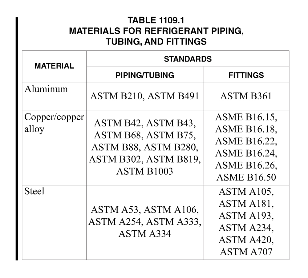
“You’ll see only a few different materials are allowed for refrigerant,” he said.
Chapter 2: Definitions
Hydronic System, Ambient Temperature Loop (ATL). An endless closed loop system comprised of centralized pumping for the circulation of the contained fluid between multiple heat exchange devices installed on the loop.
Hydronic System, District Ambient Temperature Loop. An endless closed loop system comprised of centralized pumping for the circulation of the contained fluid between multiple heat exchange devices installed on the loop. The endless loop may run exterior to conditioned spaces in order to serve multiple structures and the heat exchange devices installed within.
“The ATL is something new to the geothermal world and we really rely upon our geothermal experts to guide us in these provisions,” Young said.
Young then moved onto new appendixes.
“Appendix F is now Chapter 17 so it’s no longer a reference standard, it’s now in the code,” Young said. “Appendix H details professional qualifications. Appendix I now covers indoor horticultural facilities. Again, it’s not code, but there’s an appendix now in the UMC that addresses horticulture, growth or processing facilities.
“Appendix J, Clean Air Delivery — we talked about balancing system; this is kind of part
of it, too. It provides criteria for an increased protection level for occupant health by
delivering and monitoring clean air in certain buildings. Appendix J prepares buildings to meet increased indoor clean air delivery in response to mitgating an airborne contaminant. This has provisions where you can add outlets for future use in the event of another pandemic.”
Young then led attendees through a Kahoot quiz style game to test their knowledge of the UMC. Following the game, Young thanked attendees for their participation and concluded his presentation.
CONTENT DISCLAIMER:
The information herein is provided for educational purposes only and shall not be treated as an official interpretation of the referenced codes or standards. Always refer to the complete code or standard when installing, replacing, or repairing any plumbing or mechanical system.
GRAPHICS SOURCED FROM THE INSTRUCTOR’S SEMINAR PRESENTATION

Geoff Bilau
Last modified: June 8, 2024